Hyundai Genesis (DH): Parking Brake System / Electric Parking Brake (EPB) Repair procedures
| Removal |
| 1. |
Raise the vehicle, and make sure it is securely supported. |
| 2. |
Remove the rear tire and wheel.
|
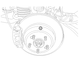
| 3. |
Remove the rear disc brake.
(Refer to Brake System - "Rear Disc Brake") |
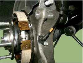
| 4. |
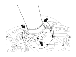
Remove the wheel speed sensor (A) by loosening the mounting bolt.
|
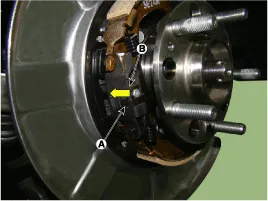
| 5. |
Remove the parking brake cable (B).
|
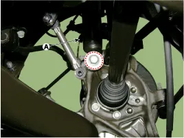
| 6. |
Remove the shock absorber mounting bolt.
|
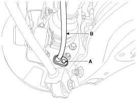
| 7. |
After making a match mark (C) on the rubber coupling (A) and
rear differential companion (B), remove the propeller shaft mounting
bolts (D).
|

| 8. |
Remove the rear cross member.
(Refer to Suspension System -"Rear Suspension System") |
| 9. |
Disconnect the EPB connector.
|
| 10. |
Separate the parking cable by loosening the bracket bolt.
|
| 11. |
Remove the EPB module.
|
| Installation |
| 1. |
Install in the reverse order of removal. |
| 2. |
Adjust the rear brake shoe clearance.
|
| 3. |
Check that the brake operates normally by pushing the EPB switch more than 3 times after installing the EPB module.
|
| Inspection |
| 1. |
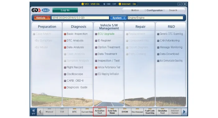
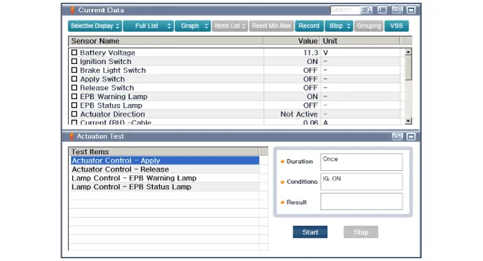
Connect the GDS to the data link connector located underneath the dash panel. |
| 1. |
Perform the item selection and operation according to the instructions on the GDS screen.
|
Schematic Diagram 1. Circuit diagram 2. Connector terminal information TerminalDescriptionCurrent (m/A) MAXMIN1Battery (+)12.5-2Battery12.5-3Parking brake switch20-4---5---6Electric parking brake switch signal 41057Electric parking brake switch signal 31058C-CAN LOW30209---10---11IGN20512---13---14Electric parking brake switch signal 210515Electric parking brake switch signal 110516C-CAN HIGH302017Ground12.
Removal 1. Turn ignition switch off and disconnect the battery (-) cable from the battery 2. Remove the driver side crash pad side cover. (Refer to Body - "Crash Pad") 3.
Other information:
Hyundai Genesis (DH) 2013-2016 Service Manual: PGS Unit (Back & Blinde Unit) Schematic Diagrams
C
Hyundai Genesis (DH) 2013-2016 Service Manual: Auto Defogging Actuator Repair procedures
Inspection 1. Turn the ignition switch OFF. 2. Disconnect the auto defogging connector. 3. Verify that the auto defogging actuator operates to the open position when connecting 12V to terminal 3 and grounding terminal 4. Verify that the auto defogging actuator operates to the close position when connected in reverse.
Categories
- Manuals Home
- Hyundai Genesis Owners Manual
- Hyundai Genesis Service Manual
- Smart Cruise Control Unit Repair procedures
- Electric Parking Brake (EPB) Repair procedures
- Steering System
- New on site
- Most important about car
