Hyundai Genesis (DH): Parking Brake System / EPB Switch Repair procedures
Hyundai Genesis (DH) 2013-2016 Service Manual / Brake System / Parking Brake System / EPB Switch Repair procedures
| Removal |
| 1. |
Turn ignition switch off and disconnect the battery (-) cable from the battery |
| 2. |
Remove the driver side crash pad side cover.
(Refer to Body - "Crash Pad") |
| 3. |
Remove the crash pad lower panel.
(Refer to Body - "Crash Pad") |
| 4. |
Remove the EPB switch after removing 4 screws from the crash pad lower panel.
|

| Inspection |
EPB Switch
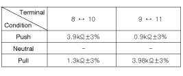
| 1. |
Measure resistance between EPB switch terminals as below.
|
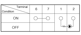
Auto Hold Switch
| 1. |
Measure resistance between Auto Hold switch terminals as below.
|
| Installation |
| 1. |
Install EPB switch assembly. |
| 2. |
Connect the crash pad switch assembly connector to EPB switch. |
| 3. |
Install the crash pad lower panel.
(Refer to Body - "Crash Pad") |
| 4. |
Install the driver side crash pad side cover.
(Refer to Body - "Crash Pad") |
Removal 1. Raise the vehicle, and make sure it is securely supported. 2. Remove the rear tire and wheel. Tightening torque : 88.3 ~ 107.9 N.
Other information:
Hyundai Genesis (DH) 2013-2016 Service Manual: Front Fog Lamps Repair procedures
Removal 1. Disconnect the negative (-) battery terminal. 2. Remove the front bumper. (Refer to Body - "Front Bumper Cover") 3. Disconnect the front fog lamp connector (A). 4. Remove the front fog lamp assembly (A) after loosening the mounting nut.
Hyundai Genesis (DH) 2013-2016 Service Manual: Specifications
S
Categories
- Manuals Home
- Hyundai Genesis Owners Manual
- Hyundai Genesis Service Manual
- Suspension System
- Starter Repair procedures
- Electric Parking Brake (EPB) Repair procedures
- New on site
- Most important about car

Copyright © 2026 www.hgenesisdh.com - 0.0216