Hyundai Genesis (DH): Indicators And Gauges / Instrument Cluster Schematic Diagrams
| Circuit Diagram |
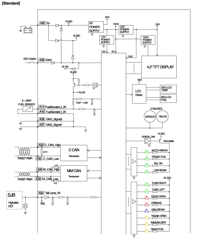
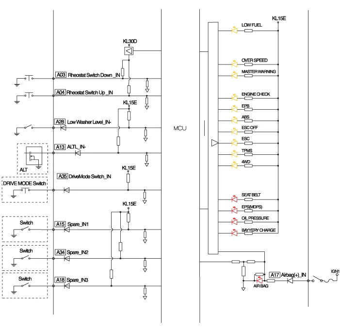
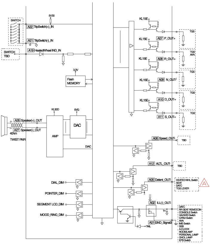
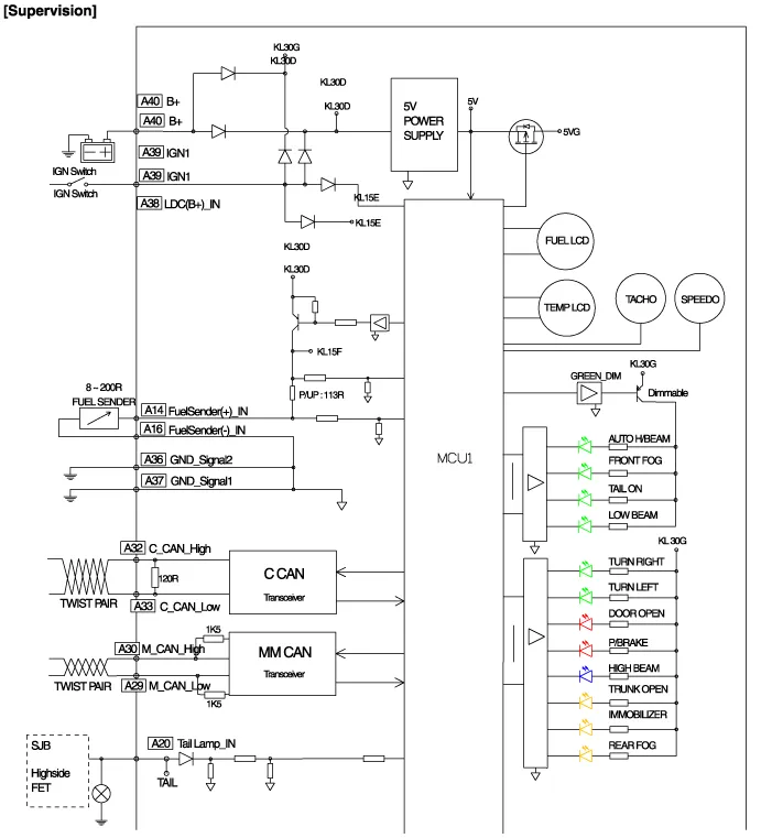
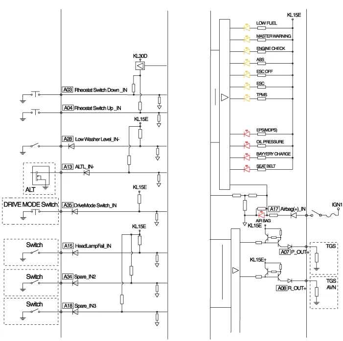
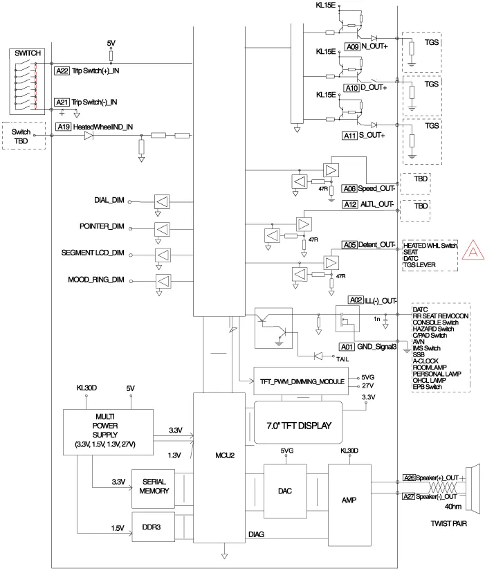
Components Connector Pin Information No.DescriptionNo.Description1-21-2Illumination output22-3Rheostat down switch234P output4Rheostat up switch24Immobilizer5AT N output25AT S output6Oil pressure26AT R output7Low washer27AT P output8Charge28-9AT D output29-10Illumination +30MM_CAN High11-31MM_CAN Low12Active ECO32C_CAN High13Heated wheel indicator33C_CAN Low14Fuel34Trip switch115Detent output35Trip switch216Fuel ground36Trip switch ground17-37Signal ground18Speaker -38-19Speaker +39IGN +20Aig bag +40Battery +
Description Communication Network Diagram AbbreviationExplanationAAFActive Air FlapACUAirbag Control UnitADMAssist Door ModuleAHDActive Hood SystemAMPAmplifierARSArmrest SwitchASCCAdvanced Smart Cruise ControlAVMAround View MonitorAWDAll Wheel DriveB_CANBody Controller Area NetworkBCMBody Control ModuleBSDBlind Spot DetectionC_CANChassis Controller Area NetworkCCPCenter Control PanelCLUMCluster ModuleDATCDual Automatic Temp ControlDDMDriver Door ModuleDisplayDisplay MonitorDSSDriver Seat SwitchECSElectronic Control SuspentionEMSEngine Management SystemEPBElectronic Parking BrakeEVPEva Vacuum PumpFPCMFuel Pump Control ModuleH/UnitHead UnitHSWSHaptic Steering Warning SystemHUDHead Up DisplayI-BOXTelematics SystemIDBIntegrated Dynamic BrakeLDWSLane Departure Warning SystemM_CANMulti media Controller Area NetworkMDPSMotor Driven Power SteeringMFSMulti-Function SwitchODSOccupant Detection SystemP_CANPowertrain Controller Area NetworkPGSParking Guide SystemPSBPre-Safe Seat BeltPSMPower Seat ModulePTLMPower Trunk Lid ModuleRRCRear Remote ControlSASSteering Angle SensorSCMSteering Column ModuleSJBSmart Junction BoxSLBSeat Lumber BolsterSMKSmart Key UnitSPASSmart Parking Assist SystemSWRCSteering Wheel Remote ControllerTCUTransmission Control UnitTPMSTire Pressure Monitoring SystemVDCVehicle Dynamic Control Refer to the "Body Network System" for the abbreviation information.
Categories
- Manuals Home
- Hyundai Genesis Owners Manual
- Hyundai Genesis Service Manual
- Engine Coolant Temperature Sensor (ECTS) Repair procedures
- Restraint
- Suspension System
- New on site
- Most important about car
