Hyundai Genesis (DH): Indicators And Gauges / Instrument Cluster Description and Operation
Hyundai Genesis (DH) 2013-2016 Service Manual / Body Electrical System / Indicators And Gauges / Instrument Cluster Description and Operation
| Description |
Communication Network Diagram
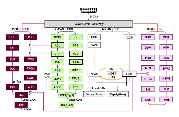
| Abbreviation | Explanation |
| AAF | Active Air Flap |
| ACU | Airbag Control Unit |
| ADM | Assist Door Module |
| AHD | Active Hood System |
| AMP | Amplifier |
| ARS | Armrest Switch |
| ASCC | Advanced Smart Cruise Control |
| AVM | Around View Monitor |
| AWD | All Wheel Drive |
| B_CAN | Body Controller Area Network |
| BCM | Body Control Module |
| BSD | Blind Spot Detection |
| C_CAN | Chassis Controller Area Network |
| CCP | Center Control Panel |
| CLUM | Cluster Module |
| DATC | Dual Automatic Temp Control |
| DDM | Driver Door Module |
| Display | Display Monitor |
| DSS | Driver Seat Switch |
| ECS | Electronic Control Suspention |
| EMS | Engine Management System |
| EPB | Electronic Parking Brake |
| EVP | Eva Vacuum Pump |
| FPCM | Fuel Pump Control Module |
| H/Unit | Head Unit |
| HSWS | Haptic Steering Warning System |
| HUD | Head Up Display |
| I-BOX | Telematics System |
| IDB | Integrated Dynamic Brake |
| LDWS | Lane Departure Warning System |
| M_CAN | Multi media Controller Area Network |
| MDPS | Motor Driven Power Steering |
| MFS | Multi-Function Switch |
| ODS | Occupant Detection System |
| P_CAN | Powertrain Controller Area Network |
| PGS | Parking Guide System |
| PSB | Pre-Safe Seat Belt |
| PSM | Power Seat Module |
| PTLM | Power Trunk Lid Module |
| RRC | Rear Remote Control |
| SAS | Steering Angle Sensor |
| SCM | Steering Column Module |
| SJB | Smart Junction Box |
| SLB | Seat Lumber Bolster |
| SMK | Smart Key Unit |
| SPAS | Smart Parking Assist System |
| SWRC | Steering Wheel Remote Controller |
| TCU | Transmission Control Unit |
| TPMS | Tire Pressure Monitoring System |
| VDC | Vehicle Dynamic Control |
Refer to the "Body Network System" for the abbreviation information. |

Cluster Variant Coding
As we have more options (ESC, TPMS, SCC, etc.) in the car,
the dashboard now have more information to display depending on the
chosen options.
For this reason, we need to learn which options the current vehicle when we replace the dashboard.
To address this issue, a course of learning based on the
option required for the vehicle when replacing the dashboard should be
carried out.
This is called Variant Coding.
Function
| 1. |
High speed CAN communication (C-CAN)
|
| 2. |
Low speed CAN communication (M-CAN)
|
| 3. |
Various source control
Various alarms and sound effects are issued through the external speakers connected to the instrument cluster.
Circuit Diagram Removal Special care is needed for the following points in case of working with the non-gloss timber trimming. Other information:Hyundai Genesis (DH) 2013-2016 Service Manual: Description and OperationDescription System Overview The System offers the following features: - Changing the state of engine ignition and power by using the start button. - Controlling external relays for ACC / IGN1 / IGN2 terminal switching and STARTER, without use of mechanical ignition switch. Hyundai Genesis (DH) 2013-2016 Service Manual: Head Up Display Unit TroubleshootingT Categories

Copyright © 2026 www.hgenesisdh.com - 0.032
|