Hyundai Genesis (DH): Indicators And Gauges / Instrument Cluster Components and Components Location
Hyundai Genesis (DH) 2013-2016 Service Manual / Body Electrical System / Indicators And Gauges / Instrument Cluster Components and Components Location
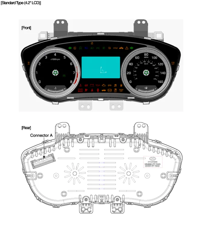
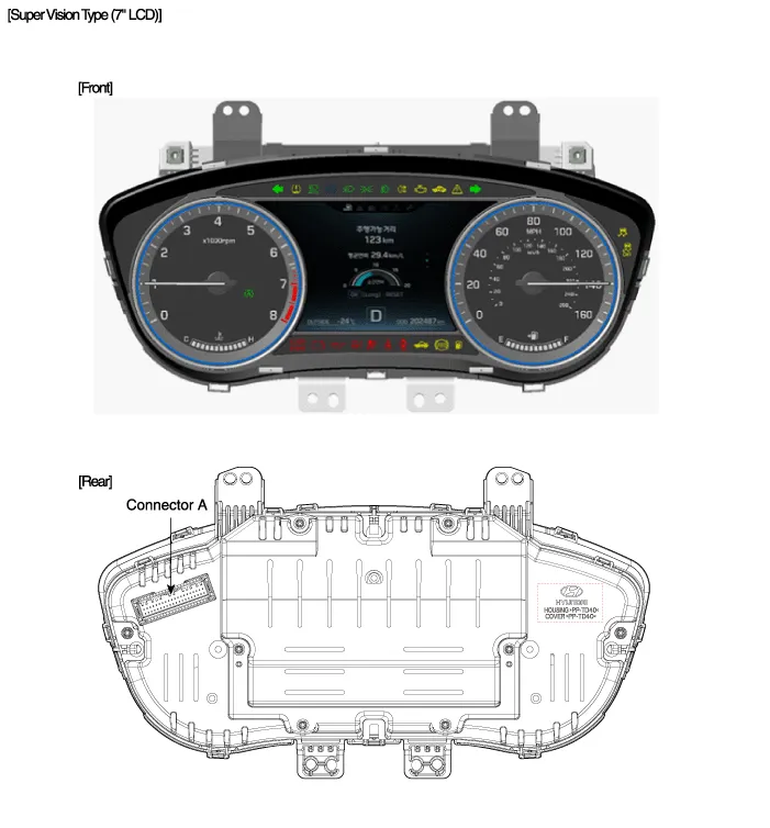
| Components |
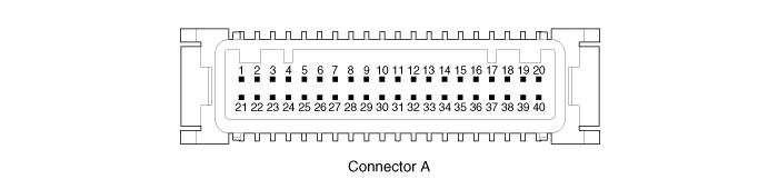
Connector Pin Information
| No. | Description | No. | Description |
| 1 | - | 21 | - |
| 2 | Illumination output | 22 | - |
| 3 | Rheostat down switch | 23 | 4P output |
| 4 | Rheostat up switch | 24 | Immobilizer |
| 5 | AT N output | 25 | AT S output |
| 6 | Oil pressure | 26 | AT R output |
| 7 | Low washer | 27 | AT P output |
| 8 | Charge | 28 | - |
| 9 | AT D output | 29 | - |
| 10 | Illumination + | 30 | MM_CAN High |
| 11 | - | 31 | MM_CAN Low |
| 12 | Active ECO | 32 | C_CAN High |
| 13 | Heated wheel indicator | 33 | C_CAN Low |
| 14 | Fuel | 34 | Trip switch1 |
| 15 | Detent output | 35 | Trip switch2 |
| 16 | Fuel ground | 36 | Trip switch ground |
| 17 | - | 37 | Signal ground |
| 18 | Speaker - | 38 | - |
| 19 | Speaker + | 39 | IGN + |
| 20 | Aig bag + | 40 | Battery + |
Circuit Diagram
Other information:
Hyundai Genesis (DH) 2013-2016 Service Manual: Console Temperature Control Actuator Repair procedures
Inspection 1. Turn the ignition switch OFF. 2. Disconnect the console temperature control actuator connector. 3. Verify that the console temperature control actuator operates to the defrost mode when connecting 12V to terminal 3 and grounding terminal 4.
Hyundai Genesis (DH) 2013-2016 Service Manual: Blower Unit Repair procedures
R
Categories
- Manuals Home
- Hyundai Genesis Owners Manual
- Hyundai Genesis Service Manual
- Repair procedures
- Restraint
- Electric Parking Brake (EPB) Repair procedures
- New on site
- Most important about car

Copyright © 2026 www.hgenesisdh.com - 0.0238