Hyundai Genesis (DH): Tire Pressure Monitoring System / TPMS Receiver Schematic Diagrams
| Circuit Diagram |
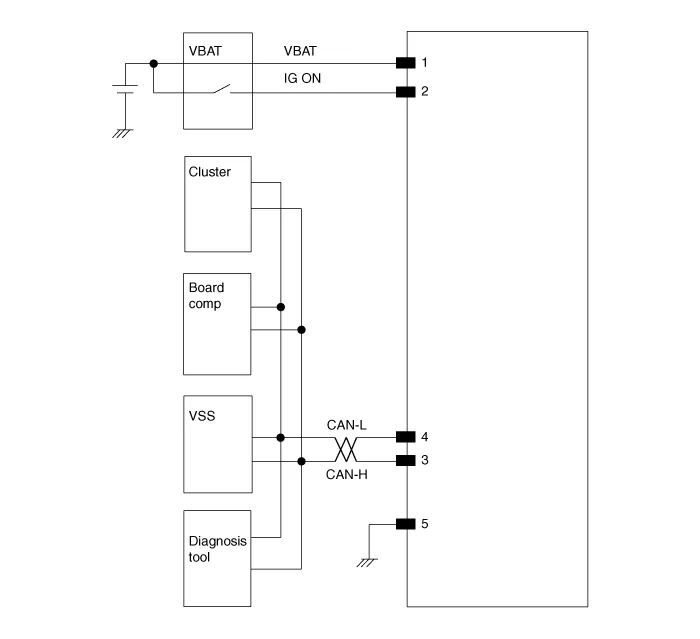
| 1. |
Circuit diagram
|
| 2. |
Receiver connector terminals.
|

| 3. |
Receiver connector function.
|
Description 1. Function The TPMS monitors the pressure and temperature of the tires and warns the driver of changes that could potentially influence driving conditions.
Replacement 1. Disconnect the negative (-) battery cable. 2. Remove the crash pad. (Refer to Body - "Crash Pad") 3. Remove the connector. 4.
Other information:
Hyundai Genesis (DH) 2013-2016 Service Manual: Start/Stop Button Repair procedures
Removal 1. Disconnect the negative(-) battery terminal. 2. Remove the driver crash pad lower panel. (Refer to Body - "Crash Pad Lower Panel") 3. Remove the start/stop button (A) from the center fascia garnish after loosening the mounting clip.
Hyundai Genesis (DH) 2013-2016 Service Manual: Compressor Description and Operation
Description The compressor is the power unit of the A/C system. It is located on the side of engine block and driven by a V-belt of the engine. The compressor changes low-pressure and low-temperature refrigerant gas into high-pressure and high-temperature refrigerant gas.
Categories
- Manuals Home
- Hyundai Genesis Owners Manual
- Hyundai Genesis Service Manual
- Front Door
- Body Electrical System
- Starter Repair procedures
- New on site
- Most important about car
