Hyundai Genesis (DH): Tire Pressure Monitoring System / TPMS Receiver Description and Operation
| Description |
| 1. |
Function
The TPMS monitors the pressure and temperature of the tires
and warns the driver of changes that could potentially influence driving
conditions.
The cluster warning lamp displays the messages generated from processing the data.
The ECU processes the data received from the WE sensor,
determines the conditions of the tire, and then sends any necessary
warning signals to the driver through the CAN line or hard wire control
line. |
| 2. |
Mode
|
| Operation |
| 1. |
General Function
|
| 2. |
General Conditions to Learn New Sensors:
|
| 3. |
General Conditions to Un-Learn a sensor that is removed:
|
Removal 1. Remove the valve core and deflate the tire. 2. Remove the side of the tire bead area from the wheel using tire changing machine .
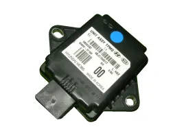
Circuit Diagram 1. Circuit diagram 2. Receiver connector terminals. 3. Receiver connector function. No FunctionDescription1BatteryVBAT2IG ONBattery to IG ON3CAN_HighCAN_High4CAN_LowCAN_Low5GroundBattery to ground6--
Other information:
Hyundai Genesis (DH) 2013-2016 Service Manual: Description and Operation
System Overview RPAS (Rear Parking Assist System) is an electronic driving aid that warns the driver to be cautious while parking or driving at low speed. The sensor uses ultrasonic waves to detect objects within proximity of the vehicle. RPAS consists of four RPS sensors which are detecting the obstacles and transmit the result separat
Hyundai Genesis (DH) 2013-2016 Service Manual: Heater Unit Components and Components Location
Component Location Components (1) 1. Shower duct (Left)2. Mode actuator (LH)3. Temperature control actuator (LH)4. Temperature door lever (Left)5. Mode actuator (A)6. Console temperature actuator (A)7. Console mode actuator ON/OFF8. Heater case (Left)9.
Categories
- Manuals Home
- Hyundai Genesis Owners Manual
- Hyundai Genesis Service Manual
- Emission Control System
- Suspension System
- Heating, Ventilation and Air Conditioning
- New on site
- Most important about car
