Hyundai Genesis (DH): Controller / Heater & A/C Control Unit Repair procedures
| Self Diagnosis |
| 1. |
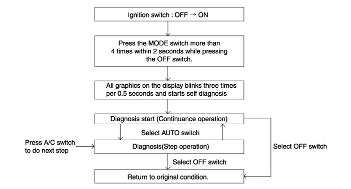
Self-diagnosis process
|
| 2. |
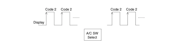
How to read self-diagnostic code
After the display panel blinks three times every 0.5 second,
the corresponding fault code blinks on the setup temperature display
panel every 0.5 second and will show two figures. Codes are displayed in
numerical format
Fault code
|
| 3. |
Fault code display
|


| 4. |
If fault codes are displayed while checking, inspect for malfunction causes by referring to the fault code table. |
| 5. |
Fail Safe
Component Connector Pin Function Pin No.Connector A functionPin No.Connector B function1Taillight (ILL+)1Ground2Sensor REF(+5v)2Diagnosis ionizer3Driver's mode control actuator (Vent)3Clean signal4Driver's mode control actuator (Defrost)4-5Driver's mode control actuator feedback5Passenger's seat belt indicator6Driver's temperature control actuator (Cooling)6Rear seat belt indicator (Left)7Driver's temperature control actuator (Heating)7Rear seat belt indicator (Center)8Driver's temperature control actuator feedback8Rear seat belt indicator (Right)9Defrost actuator (Open)9Humidity sensor10Defrost actuator (Closed)10CO2 Sensor signal11Defrost actuator feedback 11- 12Intake actuator (FRE)12Evaporator sensors(+)13Intake actuator(REF)13Rear defogging sensor14Intake actuator feedback14Heat15-15Idle Stop&Go-DC16-16Battery17-17Sensor ground18-18Console mode actuator (Rear seat vent)19K-LINE19Console mode actuator (Rear seat floor)20Leo stat (ILL-)20Console mode actuator feedback21Ignition 221Console temperature actuator (Cooling)22Mode actuator (Vent)22Console temperature actuator (Heating)23Mode actuator (Defrost)23Console temperature actuator feedback24Mode actuator feedback 24Console On/Off actuator (Off)25Driver's temperature actuator (Cooling)25Console On/Off actuator (On)26Driver's temperature actuator (Heating)26Console On/Off actuator feedback27Temperature actuator feedback 27Console temperature switch actuator 28P-CAN(HIGH)28Console On/Off actuator (On)29P-CAN(LOW)29PAB ON Sine30DETENT OUT30PAB OFF Sine31-31PAB lgnition32PTC Signal ON32 lgnition 133PTC Relay 2??34PTC Relay 3??35ECV +??36ECV- (Ground)??37Blower motor (+)??38FET (Gate)??39FET (Drain feedback)??40Ground?? Other information:Hyundai Genesis (DH) 2013-2016 Service Manual: Compressor Components and Components LocationC Hyundai Genesis (DH) 2013-2016 Service Manual: Console Temperature Control Actuator Repair proceduresInspection 1. Turn the ignition switch OFF. 2. Disconnect the console temperature control actuator connector. 3. Verify that the console temperature control actuator operates to the defrost mode when connecting 12V to terminal 3 and grounding terminal 4. Categories

Copyright © 2026 www.hgenesisdh.com - 0.022
|