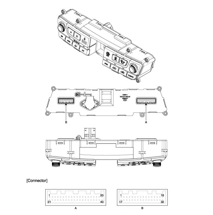
Hyundai Genesis (DH): Controller / Heater & A/C Control Unit Components and Components Location
| Component |

| Connector Pin Function |
| Pin No. | Connector A function | Pin No. | Connector B function |
| 1 | Taillight (ILL+) | 1 | Ground |
| 2 | Sensor REF(+5v) | 2 | Diagnosis ionizer |
| 3 | Driver's mode control actuator (Vent) | 3 | Clean signal |
| 4 | Driver's mode control actuator (Defrost) | 4 | - |
| 5 | Driver's mode control actuator feedback | 5 | Passenger's seat belt indicator |
| 6 | Driver's temperature control actuator (Cooling) | 6 | Rear seat belt indicator (Left) |
| 7 | Driver's temperature control actuator (Heating) | 7 | Rear seat belt indicator (Center) |
| 8 | Driver's temperature control actuator feedback | 8 | Rear seat belt indicator (Right) |
| 9 | Defrost actuator (Open) | 9 | Humidity sensor |
| 10 | Defrost actuator (Closed) | 10 | CO2 Sensor signal |
| 11 | Defrost actuator feedback | 11 | - |
| 12 | Intake actuator (FRE) | 12 | Evaporator sensors(+) |
| 13 | Intake actuator(REF) | 13 | Rear defogging sensor |
| 14 | Intake actuator feedback | 14 | Heat |
| 15 | - | 15 | Idle Stop&Go-DC |
| 16 | - | 16 | Battery |
| 17 | - | 17 | Sensor ground |
| 18 | - | 18 | Console mode actuator (Rear seat vent) |
| 19 | K-LINE | 19 | Console mode actuator (Rear seat floor) |
| 20 | Leo stat (ILL-) | 20 | Console mode actuator feedback |
| 21 | Ignition 2 | 21 | Console temperature actuator (Cooling) |
| 22 | Mode actuator (Vent) | 22 | Console temperature actuator (Heating) |
| 23 | Mode actuator (Defrost) | 23 | Console temperature actuator feedback |
| 24 | Mode actuator feedback | 24 | Console On/Off actuator (Off) |
| 25 | Driver's temperature actuator (Cooling) | 25 | Console On/Off actuator (On) |
| 26 | Driver's temperature actuator (Heating) | 26 | Console On/Off actuator feedback |
| 27 | Temperature actuator feedback | 27 | Console temperature switch actuator |
| 28 | P-CAN(HIGH) | 28 | Console On/Off actuator (On) |
| 29 | P-CAN(LOW) | 29 | PAB ON Sine |
| 30 | DETENT OUT | 30 | PAB OFF Sine |
| 31 | - | 31 | PAB lgnition |
| 32 | PTC Signal ON | 32 | lgnition 1 |
| 33 | PTC Relay 2 | ? | ? |
| 34 | PTC Relay 3 | ? | ? |
| 35 | ECV + | ? | ? |
| 36 | ECV- (Ground) | ? | ? |
| 37 | Blower motor (+) | ? | ? |
| 38 | FET (Gate) | ? | ? |
| 39 | FET (Drain feedback) | ? | ? |
| 40 | Ground | ? | ? |
Self Diagnosis 1. Self-diagnosis process 2. How to read self-diagnostic code After the display panel blinks three times every 0.5 second, the corresponding fault code blinks on the setup temperature display panel every 0.
Other information:
Hyundai Genesis (DH) 2013-2016 Service Manual: LKAS Unit Repair procedures
Removal 1. Disconnect the negative (-) battery terminal. 2. Remove the mirror wiring cover (A) and rain sensor cover (B). 3. Remove the LKAS unit connector (A). 4. Remove the LKAS unit after disengaging the mounting bracket (A). Installation 1.
Hyundai Genesis (DH) 2013-2016 Service Manual: Cluster Ionizer Repair procedures
Inspection 1. Press the MODE switch more than 4 times within 2 seconds while pressing the OFF switch. DisplayFail description00Normal51Cluster ion generator fault * For diagnostic procedure, refer to DTC guide. Replacement 1. Disconnect the negative (-) battery terminal.
Categories
- Manuals Home
- Hyundai Genesis Owners Manual
- Hyundai Genesis Service Manual
- Electric Parking Brake (EPB) Repair procedures
- Restraint
- Body (Interior and Exterior)
- New on site
- Most important about car
