Hyundai Genesis (DH): Tire Pressure Monitoring System / TPMS Receiver Repair procedures
| Replacement |
| 1. |
Disconnect the negative (-) battery cable. |
| 2. |
Remove the crash pad.
(Refer to Body - "Crash Pad") |
| 3. |
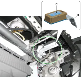
Remove the connector. |
| 4. |
Remove the bracket (B) and receiver (C) by loosening the nut (A).
|
| 5. |
Install in the reverse order of removal. |
| 6. |
Re-connect the battery, and then turn on the ignition.
|

| 7. |
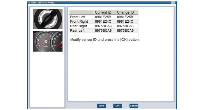
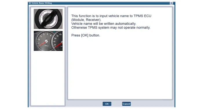
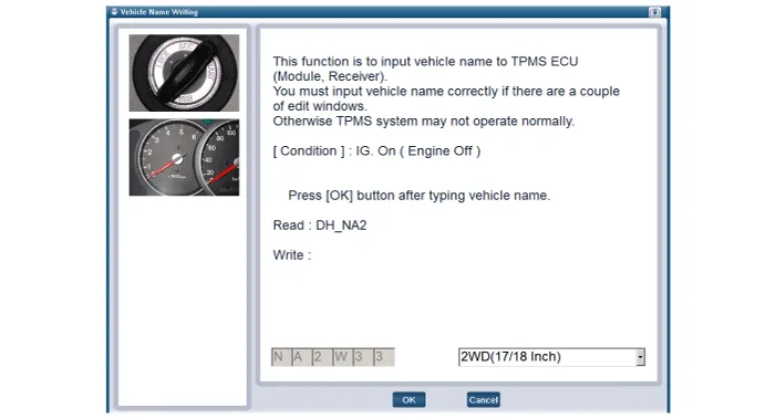
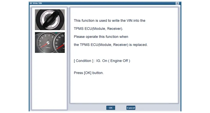
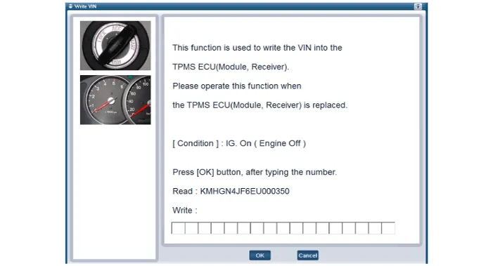
Replace the receiver, and then perform the learning process using a diagnostic instrument (GDS). |
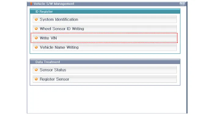
| Diagnostic Procedure Using a Diagnostic Instrument |
| 1. |
Connect the diagnostic instrument to the self-diagnostic
connector (16-pin) beneath the crash pad on the side of driver's seat,
and then turn on the ignition to activate the diagnostic instrument. |
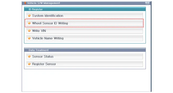
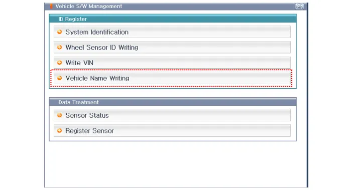
| 2. |
In the GDS Vehicle Type Selection menu, select "Vehicle Type" and "TPMS" System, and then opt for "OK." |
Circuit Diagram 1. Circuit diagram 2. Receiver connector terminals. 3. Receiver connector function. No FunctionDescription1BatteryVBAT2IG ONBattery to IG ON3CAN_HighCAN_High4CAN_LowCAN_Low5GroundBattery to ground6--
Other information:
Hyundai Genesis (DH) 2013-2016 Service Manual: Receiver-Drier Repair procedures
Replacement 1. Remove the condenser. 2. Remove the cap (B) on the bottom of the condenser with the L wrench (A). Tightening torque : 9.81 ~ 14.71 N.m (1.0 ~ 1.5 kgf.m, 7.2 ~ 10.8 lb-ft) 3. Remove the receiver-drier (A) from condenser using a long nose plier.
Hyundai Genesis (DH) 2013-2016 Service Manual: Climate Control Air Filter Repair procedures
Replacement 1. Remove both stoppers (B) by turning them from the glove box (A). 2. Disconnect the air damper (A) from the glove box (B). 3. Remove the filter cover (A) by pressing the knob. 4. Replace the air filter (A) with a new one according to the direction of air filter.
Categories
- Manuals Home
- Hyundai Genesis Owners Manual
- Hyundai Genesis Service Manual
- Steering System
- Suspension System
- Electric Parking Brake (EPB) Repair procedures
- New on site
- Most important about car
