Hyundai Genesis (DH): Fuel Delivery System / Fuel Pump Control Module (FPCM) Repair procedures
Hyundai Genesis (DH) 2013-2016 Service Manual / Engine Control / Fuel System / Fuel Delivery System / Fuel Pump Control Module (FPCM) Repair procedures
| Inspection |
| 1. |
Connect the GDS on the Data Link Connector (DLC). |
| 2. |
If there is DTC on the GDS, replace the FPCM. |
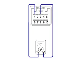
| 3. |
Check the output voltage of fuel pressure sensor (FPS).
|
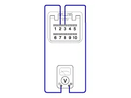
| 4. |
Check the output voltage of fuel pressure sensor (FPS) at idle.
|
| 5. |
Test the lower fuel pressure line.
(Refer to Fuel Delivery System - "Fuel Pressure Test")
|
| Removal |
| 1. |
Turn the ignition switch OFF and disconnect the battery negative (-) cable. |
| 2. |
Remove the trunk rear transverse trim. |
| 3. |
Fold the luggage side trim (LH). |
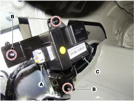
| 4. |
Disconnect the fuel pump control module connector (A). |
| 5. |
Remove the mounting nuts (B), and then remove the fuel pump control module (C) from the vehicle.
|
| Installation |
| 1. |
To install, reverse the removal procedure. |
Circuit Diagram
Description The fuel pressure sensor (FPS) is installed on top of the low pressure fuel pump and measures the pressure of the low pressure fuel line.
Other information:
Hyundai Genesis (DH) 2013-2016 Service Manual: Description and Operation
Description BSD is a system that measures the speed of and distance from the following vehicles by using two magnetic wave radar sensors attached to the rear bumper, and detects any vehicle within the blind spot zone and gives off alarm (visual and auditory).
Hyundai Genesis (DH) 2013-2016 Service Manual: Condenser Repair procedures
Inspection 1. Check the condenser fins for clogging and damage. If they are clogged, clean them with water, and blow them with compressed air. If they are bent, gently bend them using a screwdriver or pliers. 2. Check the condenser connections for leakage, and repair or replace it, if required.
Categories
- Manuals Home
- Hyundai Genesis Owners Manual
- Hyundai Genesis Service Manual
- Restraint
- Front Door
- Brake System
- New on site
- Most important about car

Copyright © 2026 www.hgenesisdh.com - 0.025