Hyundai Genesis (DH): Fuel Delivery System / Fuel Pump Control Module (FPCM) Schematic Diagrams
Hyundai Genesis (DH) 2013-2016 Service Manual / Engine Control / Fuel System / Fuel Delivery System / Fuel Pump Control Module (FPCM) Schematic Diagrams
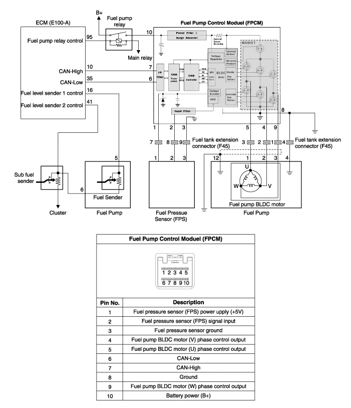
| Circuit Diagram |
Specification ltemSpecificationSupply Voltage (V)8~18Supply Current (A)Max. 10Fuel Pressure (kpa)Starting600Drive350 ~ 500Stop20 Under
Inspection 1. Connect the GDS on the Data Link Connector (DLC). 2. If there is DTC on the GDS, replace the FPCM. 3. Check the output voltage of fuel pressure sensor (FPS).
Categories
- Manuals Home
- Hyundai Genesis Owners Manual
- Hyundai Genesis Service Manual
- Heating, Ventilation and Air Conditioning
- Electric Parking Brake (EPB) Repair procedures
- Engine Electrical System
- New on site
- Most important about car

Copyright © 2026 www.hgenesisdh.com - 0.0225