Hyundai Genesis (DH): Lighting System / Door Mood Lamp Repair procedures
Hyundai Genesis (DH) 2013-2016 Service Manual / Body Electrical System / Lighting System / Door Mood Lamp Repair procedures
| Removal |
| 1. |
Disconnect the negative (-) battery terminal. |
| 2. |
Remove the front door trim.
(Refer to Body - "Front Door Trim") |
| 3. |
Disconnect the door mood lamp connectors (A).
|
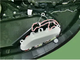
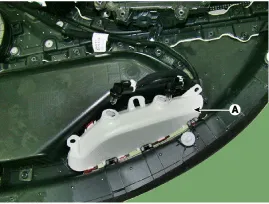
| 4. |
Remove the door mood lamp (A) after loosening the screws (3EA).
|
| 5. |
If it is necessary to replace the bulb, replace the bulb (A) after disconnecting the connector.
|
| Installation |
| 1. |
Install the door mood lamp and connector. |
| 2. |
Install the front door trim. |
| 3. |
Connect the negative (-) battery terminal. |
Inspection 1. Remove the overhead console lamp assembly and check for continuity between terminals. If the continuity is not as specified, replace the map lamp switch.
Inspection 1. Check for continuity between terminals. If the continuity is not as specified, replace the hazard lamp switch. No.Description1BAT (+)2Illumination (+)3-4Signal5Pilot lamp6-7Illumination (-)8GND Removal
Other information:
Hyundai Genesis (DH) 2013-2016 Service Manual: Blind Spot Detection Unit Repair procedures
Removal 1. Disconnect the negative (-) battery terminal. 2. Remove the rear bumper. (Refer to Body - "Rear Bumper") 3. Remove the BSD unit (A) after loosening the mounting nuts. Take care not to separate the bracket from rear bumper when removing the BSD sensor.
Hyundai Genesis (DH) 2013-2016 Service Manual: Description and Operation
D
Categories
- Manuals Home
- Hyundai Genesis Owners Manual
- Hyundai Genesis Service Manual
- Parking Assist Sensor Repair procedures
- Suspension System
- Active Air Flap(AAF) Repair procedures
- New on site
- Most important about car

Copyright © 2026 www.hgenesisdh.com - 0.0198