Hyundai Genesis (DH): Blind Spot Detection system / Blind Spot Detection Switch Components and Components Location
Hyundai Genesis (DH) 2013-2016 Service Manual / Body Electrical System / Blind Spot Detection system / Blind Spot Detection Switch Components and Components Location
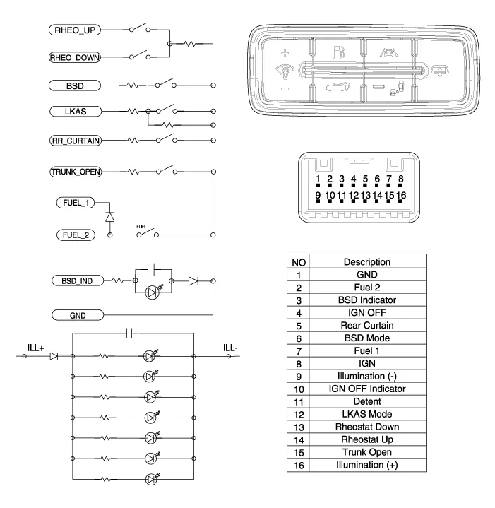
| Circuit Diagram |
Removal 1. Disconnect the negative (-) battery terminal. 2. Remove the rear bumper. (Refer to Body - "Rear Bumper") 3. Remove the BSD unit (A) after loosening the mounting nuts.
Removal 1. Disconnect the negative (-) battery terminal. 2. Remove the crash pad lower panel. (Refer to Body - "Crash Pad") 3. Remove the blind spot detection (BSD) switch (A) after disengaging the mounting clip.
Other information:
Hyundai Genesis (DH) 2013-2016 Service Manual: Auto Head Lamp Leveling Unit Repair procedures
Inspection 1. Ignition "ON". 2. Turn on the head lamp switch. 3. Check that the aim of the head lamp changes smoothly when the head lamp leveling device switch is turned on. 4. If it does not operate well, check the connector and terminals to make sure that they are connected.
Hyundai Genesis (DH) 2013-2016 Service Manual: Specifications
S
Categories
- Manuals Home
- Hyundai Genesis Owners Manual
- Hyundai Genesis Service Manual
- Electric Parking Brake (EPB) Repair procedures
- Parking Assist Sensor Repair procedures
- Description and Operation
- New on site
- Most important about car

Copyright © 2026 www.hgenesisdh.com - 0.026