Hyundai Genesis (DH): ESC(Electronic Stability Control) System / Troubleshooting
| 1. |
In principle, ESC and TCS controls are prohibited in case of ABS failure. |
| 2. |
When ESC or TCS fails, only the failed system control is prohibited. |
| 3. |
However, when the solenoid valve relay should be turned off in case of ESC failure, refer to the ABS fail-safe. |
| 4. |
Information on ABS fail-safe is identical to the one on the fail-safe in systems where ESC is not installed.
|
Memory of Fail Code
| 1. |
It keeps the code as long as the backup lamp power is ON. (O) |
| 2. |
It keeps the code as long as the HCU power is ON. (X)
|
Failure Checkup
| 1. |
Initial checkup is performed immediately after the HECU power turns ON |
| 2. |
Valve relay checkup is performed immediately after the IG2 turns ON. |
| 3. |
It executes the checkup all the time while the IG2 power is on.
|
Countermeasures in Fail
| 1. |
Turn the system down and perform the following actions and wait for the HECU power to turn off. |
| 2. |
Turn the valve relay off. |
| 3. |
Stop the control during the operation and do not execute any controls until the normal condition recovers.
|
Warning Lamp ON
| 1. |
ESC warning lamp turn on for 3sec after IGN ON. |
| 2. |
ESC function lamp blinks when the ESC is actuated |
| 3. |
If ESC failure occurs, ESC warning lamp turns ON. |
| 4. |
ESP OFF lamp turns on in the following cases:
| B. |
3 seconds after IGN ON |
|
Standard Flow of Diagnostic Troubleshooting
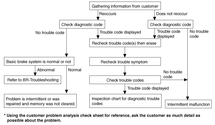
Notes With Regard To Diagnosis
The phenomena listed in the following table are not abnormal.
Condition
| Explanation
|
System check sound
| When starting the engine, a thudding sound can sometimes be heard coming
from inside the engine compartment. This is because the system operation
check is being performed.
|
ABS operation sound
|
| 1. |
Sound of the motor inside the ABS hydraulic unit operation (whine). |
| 2. |
Sound is generated along with vibration of the brake pedal (scraping). |
| 3. |
When ABS operates, sound is generated from the vehicle chassis due to
repeated brake application and release
(Thump : suspension; squeak: tires) |
|
ABS operation (Long braking distance)
| For road surfaces such as snow-covered and gravel roads, the
braking distance for vehicles with ABS can sometimes be longer than that
for other vehicles. Accordingly, advise the customer to drive safely on
such roads by lowering the vehicle speed.
|
Diagnosis detection conditions can vary depending on the diagnosis code. When checking the trouble symptom after
the diagnosis code has been erased, ensure that the requirements listed in "Comment" are met.
|
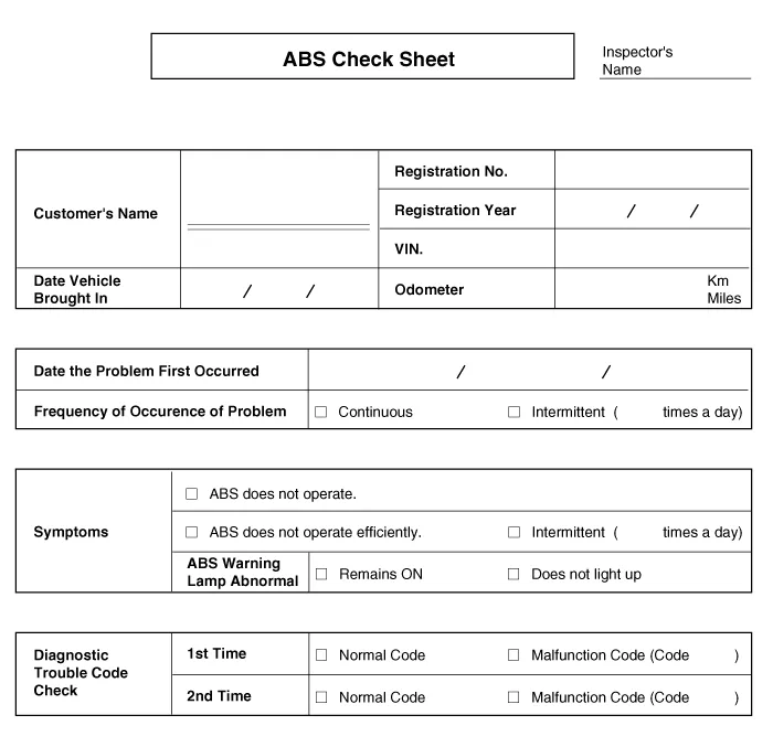
ABS Check Sheet
Problem Symptoms Table
Symptom
| Suspect Area
|
ABS does not operate.
| Only when the following 1-4 are all normal and the problem is still occurring, replace the HECU.
| 1. |
Check the DTC to reconfirm that the normal code is set. |
| 4. |
Check the hydraulic circuit for leakage. |
|
ABS does not operate intermittently.
| Only when the following 1-4 are all normal and the problem is still occurring, replace the ABS actuator assembly.
| 1. |
Check the DTC to reconfirm that the normal code is output. |
| 2. |
Wheel speed sensor circuit. |
| 3. |
Stop lamp switch circuit. |
| 4. |
Check the hydraulic circuit for leakage. |
|
Communication with GDS
is not possible.
(Communication with any system is
not possible)
|
|
Communication with GDS
is not possible.
(Communication with ABS only is
not possible)
|
|
When ignition key is turned ON
(engine OFF),
the ABS warning lamp does not light up.
|
| 1. |
ABS warning lamp circuit |
|
Even after the engine is started, the ABS
warning lamp remains ON.
|
| 1. |
ABS warning lamp circuit |
|
|
During ABS operation, the brake pedal may vibrate or may not
be able to be depressed. Such phenomena are due to intermittent changes
in hydraulic pressure inside the brake line to prevent the wheels from
locking and is not an abnormality. |

Detecting condition
Trouble Symptoms
| Possible Cause
|
Brake operation varies depending on driving conditions and road
surface conditions, so diagnosis can be difficult. However if a normal
DTC is displayed, check the following probable cause. When the problem
is still occurring, replace the ABS control module.
|
| - |
Faulty power source circuit |
| - |
Faulty wheel speed sensor circuit |
| - |
Faulty hydraulic circuit for leakage |
|
Inspection procedures
DTC Inspection
| 1. |
Connect the GDS with the data link connector and turn the ignition switch ON. |
| 2. |
Verify that the DTC code is output. |
| 3. |
Is the DTC code output?

| ? Check the power source circuit.
| 
| ? Erase the DTC and recheck using GDS.
|
|
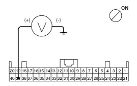
Check the power source circuit
| 1. |
Disconnect the connector from the ABS control module. |
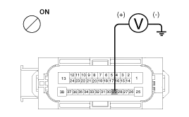
| 2. |
Turn the ignition switch ON, measure the voltage between
terminal 29 of the ABS control module harness side connector and body
ground.
Specification: approximately B+
|
|
| 3. |
Is the voltage within specification?
| ? Check the ground circuit.
|
| ? Check the harness or connector between the fuse (10A) in
the engine compartment junction block and the ABS control module. Repair
if necessary.
|
|
Check the ground circuit
| 1. |
Disconnect the connector from the ABS control module. |
| 2. |
Check for continuity between terminals 13, 38 of the ABS control module harness side connector and ground point. 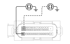
|
| 3. |
Is there continuity?
| ? Check the wheel speed sensor circuit.
|
| ? Repair an open in the wire and ground point.
|
|
Check the wheel speed sensor circuit
| 1. |
Refer to the DTC troubleshooting procedures. |
| 2. |
Is it normal?
| ? Check the hydraulic circuit for leakage.
|
| ? Repair or replace the wheel speed sensor.
|
|
Check the hydraulic circuit for leakage
| 1. |
Refer to the hydraulic lines. |
| 2. |
Inspect the leakage of the hydraulic lines. |
| 3. |
Is it normal?
| ? The problem is still occurring, replace the ABS control module.
|
| ? Repair the hydraulic lines for leakage.
|
|

Detecting condition
Trouble Symptoms
| Possible Cause
|
Brake operation varies depending on driving conditions and road
surface conditions, so diagnosis can be difficult. However if a normal
DTC is displayed, check the following probable cause. When the problem
is still occurring, replace the ABS control module.
|
| - |
Faulty power source circuit |
| - |
Faulty wheel speed sensor circuit |
| - |
Faulty hydraulic circuit for leakage |
|
Inspection procedures
DTC Inspection
| 1. |
Connect the GDS with the data link connector and turn the ignition switch ON. |
| 2. |
Verify that the DTC code is set. |
| 3. |
Is the DTC code output?
| ? Check the wheel speed sensor circuit.
|
| ? Erase the DTC and recheck using GDS.
|
|
Check the wheel speed sensor circuit
| 1. |
Refer to the DTC troubleshooting procedures. |
| 2. |
Is it normal?
| ? Check the stop lamp switch circuit.
|
| ? Repair or replace the wheel speed sensor.
|
|
Check the stop lamp switch circuit
| 1. |
Check that stop lamp lights up when brake pedal is depressed and turns off when brake pedal is released. |
| 2. |
Measure the voltage between terminal 23 of the ABS control
module harness side connector and body ground when brake pedal is
depressed.
Specification : approximately B+
|
|
| 3. |
Is the voltage within specification?
| ? Check the hydraulic circuit for leakage.
|
| ? Repair the stop lamp switch. Repair an open in the wire between the ABS control module and the stop lamp switch.
|
|
Check the hydraulic circuit for leakage
| 1. |
Refer to the hydraulic lines. |
| 2. |
Inspection leakage of the hydraulic lines. |
| 3. |
Is it normal?
| ? The problem is still occurring, replace the ABS control module.
|
| ? Repair the hydraulic lines for leakage.
|
|

Detecting condition
Trouble Symptoms
| Possible Cause
|
Possible defect in the power supply system (including ground) for the diagnosis line.
|
| - |
Faulty power source circuit |
|
Inspection procedures
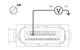
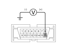
Check the Power Supply Circuit For the Diagnosis
| 1. |
Measure the voltage between terminal 16 of the data link connector and body ground.
Specification : approximately B+
|
|
| 2. |
Is voltage within specification?
| ? Check the ground circuit for the diagnosis.
|
| ? Repair an open in the wire. Check and replace fuse from the engine compartment junction block.
|
|
Check the ground circuit for the diagnosis
| 1. |
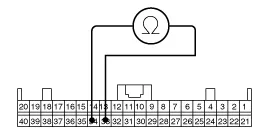
Check for continuity between terminal 4 of the data link connector and body ground. 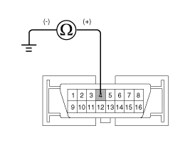
|
| 2. |
Is there continuity?
| ? Repair an open in the wire between terminal 4 of the data link connector and ground point.
|
|

Detecting condition
Trouble Symptoms
| Possible Cause
|
When communication with GDS is not possible, the cause may be
probably an open in the HECU power circuit or an open in the diagnosis
output circuit.
|
| - |
Faulty power source circuit |
|
Inspection procedures
Check for Continuity in the CAN Line
| 1. |
Disconnect the connector from the ABS control module. |
| 2. |
Check for continuity between terminals 26, 14 of the ABS control module connector and 3, 11 of the data link connector. |
| 3. |
Is there continuity?
| ? Check the power source of ABS control module.
|
| ? Repair an open in the wire.
|
|
Check the power source of ABS control module
| 1. |
Disconnect the connector from the ABS control module. |
| 2. |
Turn the ignition switch ON, measure the voltage between
terminal 29 of the ABS control module harness side connector and body
ground.
Specification : approximately B+
|
|
| 3. |
Is voltage within specification?
| ? Check for poor ground.
|
| ? Check the harness or connector between the fuse (10A) in
the engine compartment junction block and the ABS control module.Repair
if necessary.
|
|
Check for poor ground
| 1. |
Check for continuity between terminal 4 of the data link connector and ground point.
| ? Replace the ABS control module and recheck.
|
| ? Repair an open in the wire or poor ground
|
|

Detecting condition
Trouble Symptoms
| Possible Cause
|
When current flows in the HECU the ABS warning lamp turns from ON
to OFF as the initial check. Therefore if the lamp does not light up, the
cause may be an open in the lamp power supply circuit, a blown bulb,
an open in the both circuits between the ABS warning lamp and the
HECU, and the faulty HECU.
|
| - |
Faulty ABS warning lamp bulb |
| - |
Blown fuse is related to ABS in the engine compartment junction block |
| - |
Faulty ABS warning lamp module |
|
Inspection procedures
Problem verification
| 1. |
Disconnect the connector from the ABS control module and turn the ignition switch ON. |
| 2. |
Does the ABS warning lamp light up?
| ? Inspect again after replacing the ABS HECU.
|
| ? Check the power source for the ABS warning lamp.
|
|
Check the power source for the ABS warning lamp
| 1. |
Disconnect the instrument cluster connector (M08) and turn the ignition switch ON. |
| 2. |
Measure the voltage between terminal (M08) 39 of the cluster harness side connector and body ground.
Specification : approximately B+
|
|
| 3. |
Is voltage within specification?
| ? Check the CAN circuit resistance for ABS warning lamp.
|
| ? Check for blown fuse.
|
|
Check the CAN circuit resistance for ABS warning lamp
| 1. |
Disconnect the instrument cluster connector (M08) and turn the ignition switch OFF. |
| 2. |
Measure the resistance between terminal (M08) 33 and 34 of the cluster harness side connector.
|
| 3. |
Is resistance within specification?
| ? Repair ABS warning lamp bulb or instrument cluster assembly.
|
| ? Check the CAN circuit wiring for ABS warning lamp.
|
|
Check the CAN circuit wiring for ABS warning lamp
| 1. |
Disconnect the instrument cluster connector (M08) and ABS HECU connector, and then turn the ignition switch OFF. |
| 2. |
Check for continuity between terminal (M08) 33 of the cluster harness side connector and terminal 26 of ABS HECU harness side.
Check for continuity between terminal (M08) 34 of the cluster harness side connector and terminal 14 of ABS HECU harness side.
|
| 3. |
Is resistance within specification?
| ? Repair short of wiring between terminal 26, 14 of ABS HECU harness connector and ABS warning lamp module.
|
| ? Repair open of wiring between terminal 26, 14 of ABS HECU harness connector and ABS warning lamp module.
|
|

Detecting condition
Trouble Symptoms
| Possible Cause
|
If the HECU detects trouble, it lights the ABS warning lamp while at the
same time prohibiting ABS control. At this time, the HECU records a
DTC in memory. Even though the normal code is set, the ABS
warning lamp remains ON, then the cause may be probably an open
or short in the ABS warning lamp circuit.
|
| - |
Faulty instrument cluster assembly |
| - |
Faulty ABS warning lamp module |
|
Inspection procedures
Check DTC Output
| 1. |
Connect the GDS to the 16P data link connector located behind the driver's side kick panel. |
| 2. |
Check the DTC output using GDS. |
| 3. |
Is DTC output?
| ? Perform the DTC troubleshooting procedure (Refer to DTC troubleshooting).
|
| ? Check the CAN circuit resistance for ABS warning lamp.
|
|
Check the CAN circuit resistance for ABS warning lamp
| 1. |
Disconnect the instrument cluster connector (M08) and turn the ignition switch OFF. |
| 2. |
Measure the resistance between terminal (M08) 33 and 34 of the cluster harness side connector.
|
| 3. |
Is resistance within specification?
| ? Repair ABS warning lamp bulb or instrument cluster assembly.
|
| ? Check the CAN circuit wiring for ABS warning lamp.
|
|
Check the CAN circuit wiring for ABS warning lamp
| 1. |
Disconnect the instrument cluster connector (M08) and ABS HECU connector, and then turn the ignition switch OFF. |
| 2. |
Check for continuity between terminal (M08) 33 of the cluster harness side connector and terminal 26 of ABS HECU harness side.
Check for continuity between terminal (M08) 34 of the cluster harness side connector and terminal 14 of ABS HECU harness side.
|
| 3. |
Is resistance within specification?
| ? Repair short of wiring between terminal 26, 14 of ABS HECU harness connector and ABS warning lamp module.
|
| ? Repair open of wiring between terminal 26, 14 of ABS HECU harness connector and ABS warning lamp module.
|
|
Circuit Diagram
ESC connector input/output
Pin NoDescriptionCurrent(m/A)Resistance(m/?)MAX1Battery 2 (+) 137102POWERTRAIN CAN LOW302503---4---5---6---7---8---9---10---11Parking brake switch1025012---13Ground1371014POWERTRAIN CAN HIGH3025015Auto Hold Switch 1025016Stop Lamp Switch1025017Wheel speed sensor output1625018Front wheel Sensor power RH 3025019Rear wheel Sensor power RH 3025020Rear wheel Sensor signal LH 16.
Operation
The EBD system (Electronic Brake force Distribution) as a
sub-system of the ABS system is to control the maximum braking
effectiveness by the rear wheels.
Other information:
Removal
1.
Disconnect the negative (-) battery terminal.
2.
After loosening the nuts (4EA) holding the rear combination
lamp and disconnecting the connector (A), remove the outside rear
combination lamp assembly.
3.
Remove the bulb (A) after turning it in the counter clock-wise direction.
Removal
1.
Disconnect the negative (-) battery terminal.
2.
Remove the glove box housing (A).
(Refer to Body - "Glove Box")
3.
Remove the PGS unit (A) after loosening the nuts.
Installation
1.
Install the PGS unit.
2.
Install the glove box housing.

