Hyundai Genesis (DH): ESC(Electronic Stability Control) System / Schematic Diagrams
| Circuit Diagram |
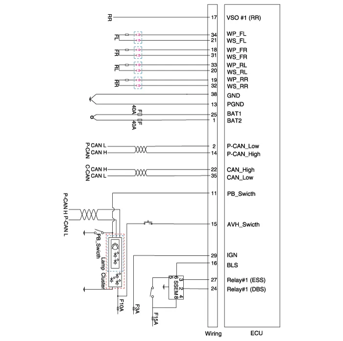
| Pin No | Description | Current(m/A) | Resistance(m/?) | |
| MAX | ||||
| 1 | Battery 2 (+) | 137 | 10 | |
| 2 | POWERTRAIN CAN LOW | 30 | 250 | |
| 3 | - | - | - | |
| 4 | - | - | - | |
| 5 | - | - | - | |
| 6 | - | - | - | |
| 7 | - | - | - | |
| 8 | - | - | - | |
| 9 | - | - | - | |
| 10 | - | - | - | |
| 11 | Parking brake switch | 10 | 250 | |
| 12 | - | - | - | |
| 13 | Ground | 137 | 10 | |
| 14 | POWERTRAIN CAN HIGH | 30 | 250 | |
| 15 | Auto Hold Switch | 10 | 250 | |
| 16 | Stop Lamp Switch | 10 | 250 | |
| 17 | Wheel speed sensor output | 16 | 250 | |
| 18 | Front wheel Sensor power RH | 30 | 250 | |
| 19 | Rear wheel Sensor power RH | 30 | 250 | |
| 20 | Rear wheel Sensor signal LH | 16.8 | 250 | |
| 21 | Front wheel Sensor signal LH | 16.8 | 250 | |
| 22 | C-CAN HIGH | 30 | 250 | |
| 23 | - | - | - | |
| 24 | DBC/HAC relay control | 250 | 250 | |
| 25 | Battery 1 (+) | 40 | 10 | |
| 26 | - | - | - | |
| 27 | ESS relay control | 250 | 250 | |
| 28 | - | - | - | |
| 29 | HECU (IGN) | 50 | 60 | |
| 30 | - | - | - | |
| 31 | Front wheel Sensor signal RH | 16.8 | 250 | |
| 32 | Rear wheel Sensor signal RH | 16.8 | 250 | |
| 33 | Rear wheel Sensor power LH | 30 | 250 | |
| 34 | Front wheel Sensor power LH | 30 | 250 | |
| 35 | C-CAN LOW | 30 | 250 | |
| 36 | - | - | - | |
| 37 | - | - | - | |
| 38 | Ground | 40 | 10 |
Description of ESC ESC recognizes critical driving conditions, such as panic reactions in dangerous situations, and stabilizes the vehicle by braking by wheel and engine control intervention.
Failure Diagnosis 1. In principle, ESC and TCS controls are prohibited in case of ABS failure. 2. When ESC or TCS fails, only the failed system control is prohibited.
Other information:
Hyundai Genesis (DH) 2013-2016 Service Manual: Head Up Display Unit Repair procedures
Removal 1. Disconnect the negative (-) battery terminal. 2. Remove the head up display bezel (A). 3. Remove the instrument cluster. (Refer to Indicators And Guages - "Instrument Cluster") 4. Remove the head up display unit bracket (A) after loosening the mounting nuts.
Hyundai Genesis (DH) 2013-2016 Service Manual: Intake Actuator Repair procedures
Inspection 1. Turn the ignition switch OFF. 2. Disconnect the intake actuator connector. 3. Verify that the intake actuator operates to the fresh position when connecting 12V to terminal 3 and grounding terminal 4. Verify that the intake actuator operates to the recirculation position when connected in reverse.
Categories
- Manuals Home
- Hyundai Genesis Owners Manual
- Hyundai Genesis Service Manual
- Active Air Flap(AAF) Repair procedures
- Steering System
- Brake System
- New on site
- Most important about car
