Hyundai Genesis (DH): Parking Guide System (PGS) / PGS Unit (Back & Blinde Unit) Repair procedures
Hyundai Genesis (DH) 2013-2016 Service Manual / Body Electrical System / Parking Guide System (PGS) / PGS Unit (Back & Blinde Unit) Repair procedures
| Removal |
| 1. |
Disconnect the negative (-) battery terminal. |
| 2. |
Remove the glove box housing (A).
(Refer to Body - "Glove Box") |
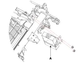
| 3. |
Remove the PGS unit (A) after loosening the nuts.
|
| Installation |
| 1. |
Install the PGS unit. |
| 2. |
Install the glove box housing. |
| 3. |
Connector the negative (-) battery terminal. |
Circuit Diagram Input / Output Terminal Voltage No.SignalDescriptionlevel1ACCACCOFF(Less than 1V), ON(More than 8V)4C-CAN-LHigh Speed CAN low-11V-OUTVideo Out-13IGNIGN SignalON(More than 9V) / OFF(Less than 1V)16C-CAN-HHigh Speed CAN high-18GND-RRear Camera GND-19REAR-POWERVCC-REARON(6~7V) / OFF(Less than 1V)20V-IN-RRear Video Input-20VGND-RRear Video Gnd-22SERIAL LINETop View Control-24VGNDVideo Out GND-
Other information:
Hyundai Genesis (DH) 2013-2016 Service Manual: Components and Components Location
C
Hyundai Genesis (DH) 2013-2016 Service Manual: Condenser Repair procedures
Inspection 1. Check the condenser fins for clogging and damage. If they are clogged, clean them with water, and blow them with compressed air. If they are bent, gently bend them using a screwdriver or pliers. 2. Check the condenser connections for leakage, and repair or replace it, if required.
Categories
- Manuals Home
- Hyundai Genesis Owners Manual
- Hyundai Genesis Service Manual
- Heating, Ventilation and Air Conditioning
- Electric Parking Brake (EPB) Repair procedures
- Active Air Flap(AAF) Repair procedures
- New on site
- Most important about car

Copyright © 2026 www.hgenesisdh.com - 0.0323