Hyundai Genesis (DH): Parking Guide System (PGS) / PGS Unit (Back & Blinde Unit) Schematic Diagrams
| Circuit Diagram |
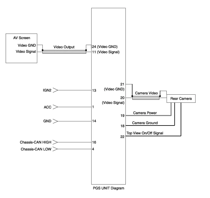
| No. | Signal | Description | level |
| 1 | ACC | ACC | OFF(Less than 1V), ON(More than 8V) |
| 4 | C-CAN-L | High Speed CAN low | - |
| 11 | V-OUT | Video Out | - |
| 13 | IGN | IGN Signal | ON(More than 9V) / OFF(Less than 1V) |
| 16 | C-CAN-H | High Speed CAN high | - |
| 18 | GND-R | Rear Camera GND | - |
| 19 | REAR-POWER | VCC-REAR | ON(6~7V) / OFF(Less than 1V) |
| 20 | V-IN-R | Rear Video Input | - |
| 20 | VGND-R | Rear Video Gnd | - |
| 22 | SERIAL LINE | Top View Control | - |
| 24 | VGND | Video Out GND | - |
Removal 1. Disconnect the negative (-) battery terminal. 2. Remove the glove box housing (A). (Refer to Body - "Glove Box") 3. Remove the PGS unit (A) after loosening the nuts.
Other information:
Hyundai Genesis (DH) 2013-2016 Service Manual: Parking Assist Sensor Repair procedures
Removal 1. Disconnect the negative (-) battery terminal. 2. Remove the front/rear bumper cover. (Refer to Body - "Front Bumper Cover") (Refer to Body - "Rear Bumper Cover") 3. Disconnect the connector (B) from the parking assist sensor (A).
Hyundai Genesis (DH) 2013-2016 Service Manual: In-car Sensor Description and Operation
Description An in-car air temperature sensor is located in the crash pad lower panel. The sensor contains a thermistor which measures the temperature of the cabin. The signal determined by the resistance value which changes in accordance with perceived inside temperature, is delivered to the heater control unit and according to this signa
Categories
- Manuals Home
- Hyundai Genesis Owners Manual
- Hyundai Genesis Service Manual
- Body (Interior and Exterior)
- Front Door
- Engine Mechanical System
- New on site
- Most important about car
