Hyundai Genesis (DH): Front Suspension System / Sub Frame Repair procedures
Hyundai Genesis (DH) 2013-2016 Service Manual / Suspension System / Front Suspension System / Sub Frame Repair procedures
| Removal |
| 1. |
Loosen the wheel nuts slightly. Raise the vehicle, and make sure it is securely supported. |
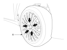
| 2. |
Remove the front wheel and tire (A) from the front hub.
|

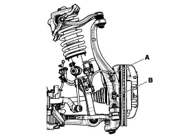
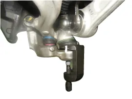
| 3. |
Remove the wheel speed sensor by loosening the wheel speed sensor bracket bolt (A) and wheel speed sensor mounting bolt (B).
[4WD]
|
| 4. |
Loosen the wheel speed sensor bracket bolt and then disconnect the wheel speed sensor connector(A).
[2WD]
|

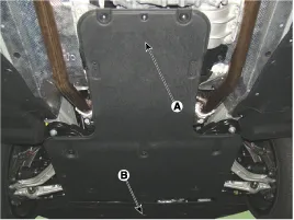
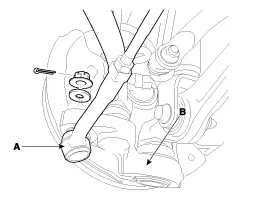
| 5. |
Remove the under cover (A) & (B).
|
| 6. |
Remove the tie rod end ball joint from the knuckle.
|


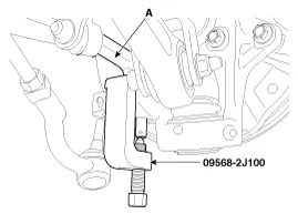
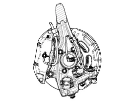
| 7. |
Remove the tension arm (A) from the knuckle by using the SST (09568-2J100).
[2WD]
|
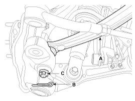
| 8. |
Loosen the nut and then remove the compression arm using SST (09568-2j100).
[4WD]
|
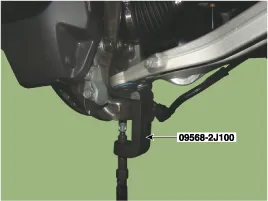
| 9. |
Loosen the nut and then remove the lateral arm using SST (09568-2j100).
[2WD]
[4WD]
|
| 10. |
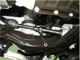
Unscrew the steering universal joint bolt (A) to disconnect the universal joint assembly from the steering gear box.
|