Hyundai Genesis (DH): Front Suspension System / Front Stabilizer Bar Repair procedures
Hyundai Genesis (DH) 2013-2016 Service Manual / Suspension System / Front Suspension System / Front Stabilizer Bar Repair procedures
| Removal |
| 1. |
Loosen the wheel nuts slightly. Raise the vehicle, and make sure it is securely supported. |
| 2. |
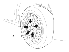
Remove the front wheel and tire (A) from the front hub.
|

| 3. |
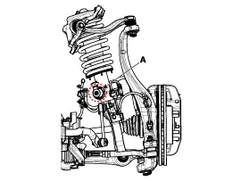
Loosen the nut (A) and disconnect the stabilizer link from the front strut assembly.
[ECS]
[HPD]
|
| 4. |
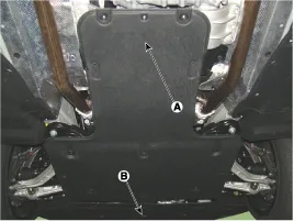
Remove the under cover (A) & (B).
|
| 5. |
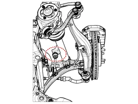
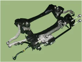
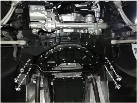
Loosen clamp mounting bolts and then separate the stabilizer bar from the subframe.
[4WD]
[2WD]
|
| 6. |
Install in the reverse order of removal. |
| 7. |
Check the alignment.
(Refer to Tires/Wheels - "Alignment") |
| Inspection |
| 1. |
Check the bushing for wear and deterioration. |
| 2. |
Check the ball joint for rotating torque. |
Replacement [4WD] Remove the lateral arm 1. Loosen the wheel nuts slightly. Raise the vehicle, and make sure it is securely supported. 2. Remove the front wheel and tire (A) from the front hub.
Removal 1. Loosen the wheel nuts slightly. Raise the vehicle, and make sure it is securely supported. 2. Remove the front wheel and tire (A) from the front hub.
Other information:
Hyundai Genesis (DH) 2013-2016 Service Manual: Components and Components Location
C
Hyundai Genesis (DH) 2013-2016 Service Manual: Blind Spot Detection Switch Repair procedures
Removal 1. Disconnect the negative (-) battery terminal. 2. Remove the crash pad lower panel. (Refer to Body - "Crash Pad") 3. Remove the blind spot detection (BSD) switch (A) after disengaging the mounting clip. Installation 1. Install the crash pad side switch assembly after connecting the connector.
Categories
- Manuals Home
- Hyundai Genesis Owners Manual
- Hyundai Genesis Service Manual
- Front Door
- Body (Interior and Exterior)
- Heating, Ventilation and Air Conditioning
- New on site
- Most important about car

Copyright © 2026 www.hgenesisdh.com - 0.0248