Hyundai Genesis (DH): Differential Carrier Assembly / Rear Differential Carrier Components and Components Location
Hyundai Genesis (DH) 2013-2016 Service Manual / Driveshaft and axle / Differential Carrier Assembly / Rear Differential Carrier Components and Components Location
| Component |
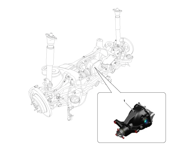
| 1. Rear differential carrier assembly |
| Component |
| [With Lambda Engine] |
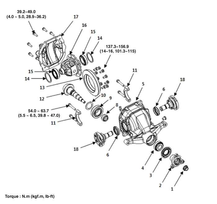
| 1. Pinion lock nut 2. Companion flange 3. Pinion oil seal 4. Pinion front bearing 5. Differential carrier 6. Side oil seal | 7. Drain plug 8. Pinion bearing spacer 9. Pinion rear bearing 10. Inner bearing adjustment shims 11. Bearing cap 12. Drive gear | 13. Ring gear 14. Spacer 15. Side bearing outer race 16. Differential case assembly 17. Differential rear cover 18. Companion shaft |
| [With Tau Engine] |
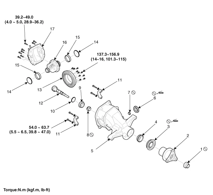
| 1. Pinion lock nut 2. Companion flange 3. Pinion oil seal 4. Pinion front bearing 5. Differential carrier 6. Side oil seal | 7. Drain plug 8. Pinion bearing spacer 9. Pinion rear bearing 10. Inner bearing adjustment shims 11. Bearing cap 12. Drive gear | 13. Ring gear 14. Spacer 15. Side bearing outer race 16. Differential case assembly 17. Differential rear cover |
Removal 1. Loosen the wheel nuts slightly. Raise the vehicle, and make sure it is securely supported 2. Remove the front wheel and tire (A) from the front hub.
Removal 1. Remove the rear wheel and tire (A) from the rear hub. Tightening torque: 88.3 ~ 107.9 N.m (9.0 ~ 11.0 kgf.m, 65.1 ~ 79.6 lb-ft) Be careful not to damage the hub bolts when removing the rear wheel and tire (A).
Other information:
Hyundai Genesis (DH) 2013-2016 Service Manual: Parking Assist Sensor Repair procedures
Removal 1. Disconnect the negative (-) battery terminal. 2. Remove the front/rear bumper cover. (Refer to Body - "Front Bumper Cover") (Refer to Body - "Rear Bumper Cover") 3. Disconnect the connector (B) from the parking assist sensor (A).
Hyundai Genesis (DH) 2013-2016 Service Manual: Repair procedures
R
Categories
- Manuals Home
- Hyundai Genesis Owners Manual
- Hyundai Genesis Service Manual
- Front Door
- Body (Interior and Exterior)
- Body Electrical System
- New on site
- Most important about car

Copyright © 2026 www.hgenesisdh.com - 0.0241