Hyundai Genesis: Differential Carrier Assembly / Rear Differential Carrier Repair procedures

Removal
1.
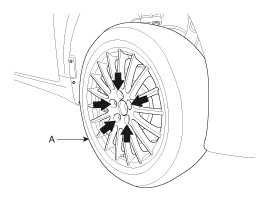
Remove the rear wheel and tire (A) from the rear hub.

Tightening torque:
88.3 ~ 107.9 N.m (9.0 ~ 11.0 kgf.m, 65.1 ~ 79.6 lb-ft)

   
Be careful not to damage the hub bolts when removing the rear wheel and tire (A).

2.
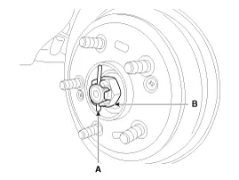
With the brake engaged, remove the split pin (A) from the rear hub and remove the castle nut (B).

Tightening torque :
196.1 ~ 274.5 N.m (20.0 ~ 28.0 kgf.m, 144.7 ~ 202.5 lb-ft)

3.
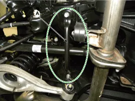
Remove the bracket (A).

Tightening torque :
49.0 ~ 63.7N.m (5.0 ~ 6.5 kgf.m, 36.2 ~ 47.0 lb-ft)

4.
Remove the muffler.
(Refer to Engine Mechanical System - "Muffler")
5.
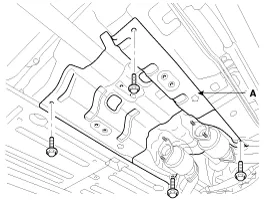
Loosen the mount bolts and then aluminum cover (A).

Tightening torque:
6.9 ~ 13.7 N.m (0.7 ~ 1.4 kgf.m, 5.1 ~ 10.1 lb-ft)

6.
Record the position of the alignment marks (C) on the rubber coupling of the propeller (A) and companion and the corresponding marks on the differential carrier (B), and then remove the propeller shaft tightening bolt (D).

Tightening torque :
88.3 ~ 107.9 N.m (9.0 ~ 11.0 kgf.m, 65.1 ~ 79.6 lb-ft)

   
Record the position of the alignment marks before removing the propeller shaft to prevent the bolt and washer from being tightened in the wrong position or the wrong direction.
Connecting the bolt and washer in the wrong direction may cause the propeller shaft to become unbalanced. This may cause the propeller shaft to vibrate at high speeds.
If the propeller shaft vibrates excessively at high speeds after replacing it or removing it from its initial mounting position, use shaft balancing equipment to properly adjust the balance of the shaft.

7.
Remove the rear driveshaft.
(Refer to Rear Driveshaft Assembly - "Rear Driveshaft")
8.
After loosening the differential mounting bolt (A-4ea) and remove the differential assembly (B).

Tightening torque:
78.5 ~ 98.1 N.m (8.0 ~ 10.0 kgf.m, 72.3 ~ 65.1 lb-ft)

9.
Install in the reverse order of removal.
Disassembly
Rear Differential Carrier Disassembly
1.
Drain oil by removing the drain plug (A).
   
Use a new washer (A) when reinstalling the drain plug.

2.
Place the differential carrier assembly in the SST (09530-3T300).

3.
Remove the filler plug (A).
   
Use a new washer (A) when reinstalling the filler plug.

4.
Remove the companion shaft. (with lambda engine)

5.
Remove the side oil seal (A) using a screwdriver.
   
Use a new oil seal when reinstalling the rear differential carrier.

6.
Loosen the bolts (A) to remove the cover (B).

   
Use a hammer and chisel when removing the differential rear cover.

7.
Remove the air breather plug (A).

8.
Remove the bearing caps (A).
   
Mark each bearing cap so that they can be reinstalled in the same position and direction.

9.
Remove the gear carrier assembly (A) using levers.

10.
Attach "Left" or "Right" tags on the bearing outer races and spacers so that they can be reinstalled in the same position.

Gear Carrier Assembly Disassembly
1.
Loosen the seal bolts and then remove the gear carrier (A) and ring gear (B).
   
Put the match marks on the gear carrier and the ring gear.

2.
Remove the side bearings using the SST (09530-3T200 or 09530-3C100).
If equipped with the Lambda engine, use the SST 09530-3T200 and if equipped with the Tau engine, use the SST (09530-3C100).
[With Lambda Engine]

[With Tau Engine]

   
A spray lubricant can be used to facilitate the removal of the bearings.

3.
Remove the bearings and then attach "Left" or "Right" tags to each bearing.

Pinion Assembly Disassembly
1.
Place the differential carrier assembly in the SST (09530-3T300).
If equipped with the Tau engine, use the additional SST (09530-3C300).
[With Lambda Engine]

[With Tau Engine]

   
Insert the dowel pin on the differential carrier case flange into the holes in the SST as shown below.

2.
Remove the pinion lock nut (A).

3.
Remove the pinion drive gear using a press.

   
Put the supports on the press as shown below to prevent the dowel pin (A) on the differential carrier case flange from damage.

4.
Remove the pinion oil seal (A) using a lever or screwdriver.

5.
Remove the pinion bearing front and rear races using a hammer and chisel.
   
Locate the end of the chisel into the grooves in the case below.
[Front]

[Rear]

6.
Press the pinion drive gear using the SST (09527-4A000) and then remove the pinion bearing spacer (A), the front bearing (B) and the inner bearing adjustment shims (C) in order.

Reassembly
   
Use the already adopted seam for controlling the inner bearing on the front differential assembly. (Use the same thickness controlling seam in case of destruction)
The rear differential assembly shall be replaced with a new one when the differential carrier or differential case assembly fails.The noise or vibration can be made due to the current inner bearing not matching the gear control seam when the carrier or differential case assembly is exchanged as a unit.
1.
Install the inner pinion bearing outer race (A) using the SST (09530-3T100).

2.
Install the outer pinion bearing outer race (A) using the SST (09530-3T100).

3.
Install the Inner bearing adjustment shim (A) to the pinion drive gear (B).

4.
Press fit the pinion rear bearing (A) using a round pipe (B).

5.
Install the SST lock nut (A), the flange (B), the pinion oil seal (C), the pinion front bearing (D), the spacer (E) and the drive gear (F) to the differential case.

(1)
Using the Round pipe (A), press in the pinion rear bearing (B).

(2)
Install the pinion bearing spacer (B) on the pinion drive gear (A).

   
Do not reuse the space. Be sure to install a new one.
(3)
Using the Round pipe (A), press in the front bearing (B).

(4)
Using the SST (09530-3T600), install the Pinion oil seal.

(5)
Using the round pipe (A), press in the companion flange (B).

6.
Install the pinion lock nut.

   
The preload must be 11.5~16.5 kgf.cm and the SST lock nut must be tightened with the torque of 0.9~1.4 N.m (9.0~14.0 kgf.cm, 0.7~1.0 lb-ft).
Preload measurements maintain the constant speed rotation (60rpm).
7.
Install the side bearing (A) using the SST (09453-3B200).
If equipped with the Tau engine, use the SST (09530-3C300).
[With Lambda Engine]

[With Tau Engine]

8.
Install the gear carrier and ring gear.

Tightening torque :
137.3 ~ 156.9 N.m (14.0 ~ 16.0 kgf.m, 101.3 ~ 115.7 lb-ft)

   
Tighten the seal bolts in the diagonal sequence.

9.
Install the left and right side adjustment spacers to the differential case.

10.
Install the left and right side bearing outer races (A) to the gear carrier.

11.
Hold the left and right side bearing outer races with both hands and install the gear carrier assembly (A) to the differential case.

12.
Install the bearing cap (A) with the match marks aligned.

Tightening torque :
53.9 ~ 63.7 Nm (5.5 ~ 6.5 kgf.m, 39.8 ~ 47.0 lb-ft)

13.
Measure the preload.

Total preload
Lambda Engine:
1.33 ~ 2.39 Nm (13.5 ~ 24.2 kgf.cm, 0.98 ~1.76 lb-ft)
Tau Engine:
1.36 ~ 2.47 Nm (13.8 ~ 25.0 kgf.cm, 1.00 ~ 1.82 lb-ft)

14.
Check the backlash.

Backlash :
0.10 ~ 0.15 mm ( 0.004~0.006 inch)

   
If the backlash exceeds the limit, make an adjustment using side bearing spacers.
If adjustment is impossible, replace the side gear and pinion gears as a set.
15.
Check the drive gear contact.
(1)
Paint the ring gear teeth with a thin coating of marking compound uniformly.

(2)
Put the ring gear into the pinion drive gear while making each painted marks aligned, and repeatedly turn the ring gear or flange clockwise and counterclockwise to check if the gear teeth are engaged properly.

(3)
Check the ring gear tooth contact pattern.
Tooth contact
Contact state
Solution
Standard contact


1. Wheel contact

Increase the thickness of the pinion height adjusting shim, and position the drive pinion closer to the center of the drive gear.
Also, for backlash adjustment, reposition the drive gearfarther from the drive pinion.

2. Face contact

3. Toe contact

Decrease the thickness of the pinion height adjusting shim, and position the drive pinion farther from the center of the drive gear.
Also, for backlash adjustment, reposition the drive gear closer to the drive pinion.

4. Flank contact


1.
Tooth contact pattern is a method for judging the result of the adjustment of drive pinion height and final drive gear backlash. The adjustment of drive pinion height and final drive gear backlash should be repeated until the tooth contact patterns are similar to the standard tooth contact pattern.
2.
If the tooth contact pattern is not correct, the drive gear and drive pinion exceed their limits. Both gears should be replaced as a set.
16.
Install the air breather (A).

Tightening torque :
9.8 ~ 19.6 Nm (1.0 ~ 2.0 kgf.m, 7.2 ~ 14.5 lb-ft)

17.
Apply the sealant (A) on the rear cover surface.

Sealant : LT5060

   
Remove the remaining sealant before coating.
Apply along the rear cover surface to the 2~3 mm of thickness evenly .

18.
Install the differential rear cover (A).

Tightening torque :
39.2 ~ 49.0 Nm (4.0 ~ 5.0 kgf.cm, 28.9 ~ 36.2 lb-ft)

19.
Install the left and right side oil seals using the SST (09530-3T000).

20.
Install the drain plug (A) and filler plug (B).

Tightening torque :
filler plug :
39.2 ~ 58.8 Nm (4.0 ~ 6.0 kgf.cm, 28.9 ~ 43.4 lb-ft)
Drain plug :
49.0 ~ 68.6 Nm (5.0 ~ 7.0 kgf.cm, 36.2 ~ 50.6 lb-ft)

21.
Install the companion shaft.

22.
Install the rear differential assembly to the vehicle and fill it with oil.

Oil type (~2015.02.28) : Hypoid gear oil MS517-15 GT 75W/90 (GL-5)
(SHELL HD AXLE OIL 75W90), SK HK G-5 75W90 Equivalent
Oil capacity (L) : 1.4 ± 0.05
Oil type (2015.03.01~) : Hypoid gear oil MS517-15 GT 75W/85 (GL-5)
(SK HK SYN GEAR OIL 75W/85  Equivalent)
Oil capacity (L) : 1.4 ± 0.05

Inspection
1.
After clearing, check the parts for damage or abrasion. Follow the method below if any problems are noticed.
Item
Identify
Gear set (drive pinion gear & drive gear)
The gear set must be replaced with a new one if the gear tooth is damaged (crack/pits/dents).
Bearing
The bearing must be replaced with a new one if the bearing roller or race is damaged (crack/pits/dents).
Oil seal
The oil seal must be replaced with a new one if disassembled.
Differential carrier
The carrier must be replaced with a new one if the inside of the carrier bearing is damaged (crack/pits/dents) or a crack is found inside/outside.
Companion flange
The pinion oil seal must be replaced with a new one if the contact surface is damaged (crack/pits/dents).
Open type
Diff gear set
(Diff side gear & diff pinion gear)
The gear set must be replaced with a new one if the gear tooth or tooth surface is damaged (crack/pits/dents).
Diff washer
(Diff side gear washer & diff pinion gear washer)
The washer must be replaced with a new one if the washer surface is damaged (crack/pits/dents).

Rear Differential Carrier Components and Components Location
Component 1. Rear differential carrier assembly Component [With Lambda Engine] 1. Pinion lock nut 2. Companion flange 3. Pinion oil seal 4. Pinion front bearing 5. Differential carrier ...

Suspension System
...

Other information:

Hyundai Genesis (DH) 2013-2016 Service Manual: Description and Operation


Description MDPS (Electric power steering, Column assist type) system uses an electric motor to assist the steering force and it is an engine operation independent steering system. MDPS control module controls the motor operation according to information received from the each sensor and ...

Hyundai Genesis (DH) 2013-2016 Service Manual: Schematic Diagrams


Circuit Diagram (1) Circuit Diagram (2) Circuit Diagram (3) SRSCM Connector terminal No.Function (Connector A)No.Function (Connector B)1IGN1Retractor pretensioner-Front,Driver-High (+)2-2Retractor pretensioner-Front,Driver-Low (-)3Driver airbag 1st stage-High (+)3Retractor pretensioner-Front ...

© 2013-2024 www.hgenesisdh.com