Hyundai Genesis: Differential Carrier Assembly / Front Differential Assembly(AWD) Repair procedures
Hyundai Genesis (DH) 2013-2016 Service Manual / Driveshaft and axle / Differential Carrier Assembly / Front Differential Assembly(AWD) Repair procedures
| Removal |
| 1. |
Loosen the wheel nuts slightly. Raise the vehicle, and make sure it is securely supported |
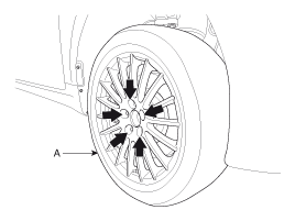
| 2. |
Remove the front wheel and tire (A) from the front hub.
|

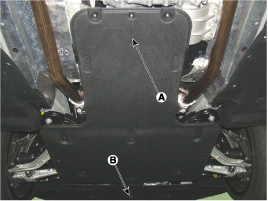
| 3. |
Remove the under cover (A) & (B).
|
| 4. |
Remove the Sub frame.
(Refer to Suspension System - "Sub Frame")
|

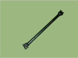
| 5. |
Remove the front propeller shaft by loosening bolts. [Both side]
|
| 6. |
Remove the steering gear box.
(Refer to Steering System - "Motor Driven Power Steering") |
| 7. |
Remove the front driveshaft.
(Refer to Driveshaft & Axle - "Front Driveshaft Assembly") |
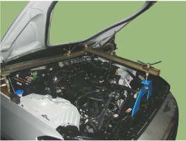
| 8. |
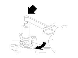
Remove the engine mount (A).
|
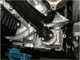
| 9. |
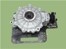
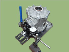
Remove the front differential assembly.
|
| 10. |
Install in the reverse order of removal. |
| Disassembly |
[Differential Case Assembly]
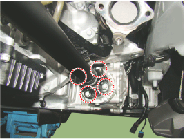
| 1. |
Drain oil by removing the drain plug (A).
|
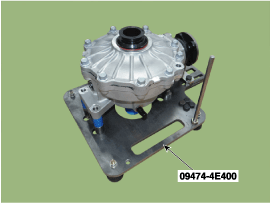
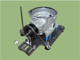
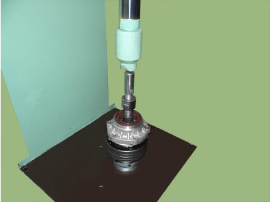
| 2. |
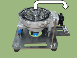
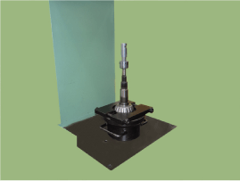
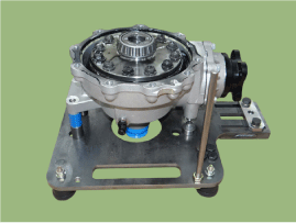
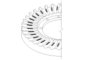
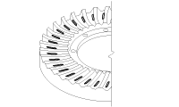
Place the front differential assembly in the SST (09474-4E400).
|
| 3. |
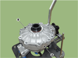
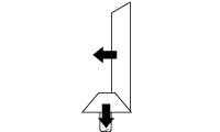
Remove the side oil seal (A) using a screwdriver.
|
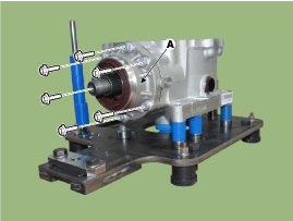
| 4. |
Loosen the bolts to remove the cover (B) from the differential carrier.
|
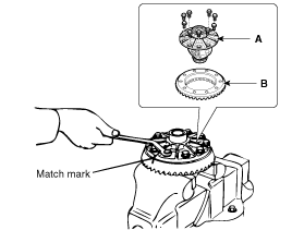
| 5. |
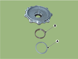
Remove the spacer (A), side bearing race (B) using a hammer and chisel.
|
| 6. |
Separate the differential case assembly from the differential carrier.
|
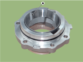
| 7. |
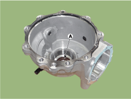
Remove the oil seal (A) from the differential carrier.
|
| 8. |
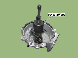
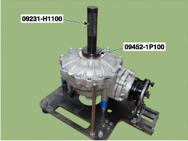
Using the SST (09452-2W300), remove the spacer & bearing race from the differential carrier.
|
| 9. |
Using the SST (09474-4E200), remove the side bearing.
|
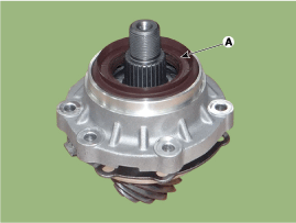
| 10. |
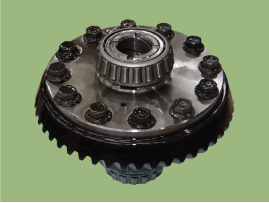
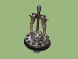
Loosen the bolts and then remove the differential case (A) and ring gear (B).
|
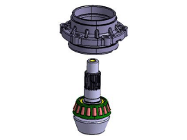
[Pinion drive gear assembly]
| 1. |
Remove the pinion cage.
|
| 2. |
Loosen the bolts and remove the pinion cage.
|
| 3. |
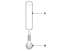
Remove the pinion drive gear assembly using a press.
|
| 4. |
Remove the pinion oil seal (A) & pinion front bearing from the pinion cage by a screwdriver.
|
| 5. |
Using a hammer and chisel, remove the pinion front bearing race (A).
|
| 6. |
Separate the pinion bearing spacer.
|
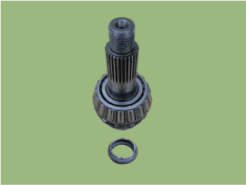
| 7. |
Using a press, remove the pinion rear bearing.
|
| Inspection |
| 1. |
After clearing, check for damage parts or abrasion. Follow the method below, if any are noticed.
| |||||||||||||||||||||||
| Reassembly |
|
[Pinion drive gear assembly]
| 1. |
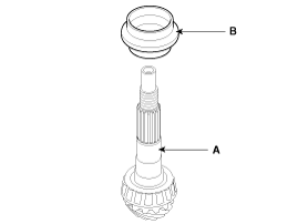
Using the Round pipe (A), press in the pinion rear bearing (B).
|
| 2. |
Install the pinion bearing spacer (B) at the pinion drive gear (A).
|
| 3. |
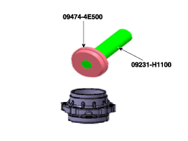
Using the SST (09452-4E500), install the pinion front bearing race.
|
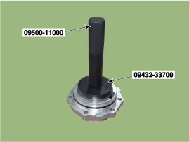
| 4. |
Using the SST (09432-33700), install the pinion rear bearing race.
|
| 5. |
After installing the pinion oil seal, install the pinion gear assembly at the pinion cage.
|
| 6. |
Install the companion flange.
|

| 7. |
Tighten the pinion lock nut.
|
| 8. |
Install the pinion O-ring.
|
| 9. |
Install the pinion sub assembly
|
[Differential case assembly]
| 1. |
Install the differential case and ring gear.
|
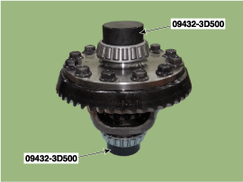
| 2. |
Using SST (09432-3D500), install the side bearing.
|
| 3. |
Uisng SST (09474-4E100), install the differential carrier oil seal.
|
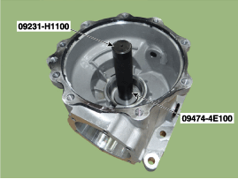
| 4. |
Using SST (09432-3D900), install a spacer and race at the differential carrier.
|
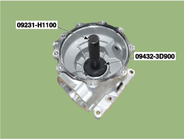
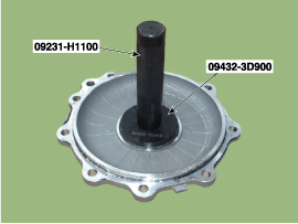
| 5. |
Using SST (09432-3D900), install a spacer and race at the differential carrier cover.
|
| 6. |
Install the differential case assembly to the differential carrier.
|
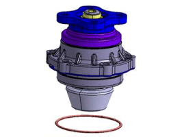
| 7. |
Check the backlash at the companion flange.
| |||||||||||||||||||||||||||||||||||||||||||||||||||||||||||||||||||||||||||||||||||||||||||||||||||||||||||||||


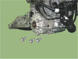
| 8. |
Install the differential carrier cover and then install the oil seal.
|
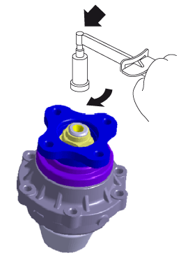
| 9. |
Measure the total preload.
|
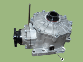
| 10. |
Install the drain plug (A).
|
| 11. |
Install the rear differential assembly to the vehicle. Loosen the filler plug (A) and fill the oil.
|
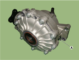
 Front Differential Assembly(AWD) Components and Components Location
Components Location
1. Front propeller shaft2. Transfer case3.Front differential assembly
Components
1. Pinion lock nut 2. Companion flange 3. Pinion oil seal 4. Pinion front bearing 5. Pin ...
 Rear Differential Carrier Components and Components Location
Component
1. Rear differential carrier assembly
Component
[With Lambda Engine]
1. Pinion lock nut 2. Companion flange 3. Pinion oil seal 4. Pinion front bearing 5. Differential carrier ...
Other information:
Hyundai Genesis (DH) 2013-2016 Service Manual: Heater & A/C Control Unit Repair procedures
Self Diagnosis 1. Self-diagnosis process 2. How to read self-diagnostic code After the display panel blinks three times every 0.5 second, the corresponding fault code blinks on the setup temperature display panel every 0.5 second and will show two figures. Codes are displayed in numer ...
Hyundai Genesis (DH) 2013-2016 Service Manual: Sunvisor Components and Components Location
Component Location 1. Sunvisor2. Retainer ...
© 2013-2025 www.hgenesisdh.com
