Hyundai Genesis (DH): Intake And Exhaust System / Surge Tank Repair procedures
Hyundai Genesis (DH) 2013-2016 Service Manual / Engine Mechanical System / Intake And Exhaust System / Surge Tank Repair procedures
| Removal and Installation |
| 1. |
Disconnect the battery "-" terminal from the trunk room. |
| 2. |
Remove the engine cover. |
| 3. |
Remove the engine room cover.
(Refer to Engine And Transaxle Assembly - "Engine Cover") |
| 4. |
Remove the Cowl Top Cover.
(Refer to Body - "Cowl Top Cover") |
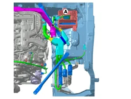
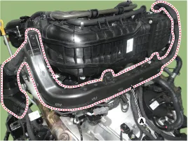
| 5. |
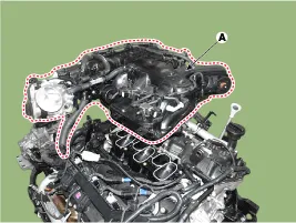
Remove the Engine room bulkhead (A).
|
| 6. |
Remove the air cleaner assembly.
(Refer to Intake Exhaust System - "Air Cleaner") |
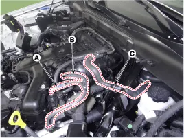
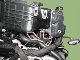
| 7. |
Disconnect the fuel hose (A,B) and Brake vacuum hose (C).
|
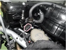
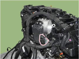
| 8. |
Disconnect the PCSV connector (A).
|
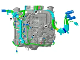
| 9. |
Disconnect the VIS connector (A), Condenser connector (B), MAP sensor connector (C).
|
| 10. |
Disconnect the throttle body connector (A).
|
| 11. |
After loosening the fixing bolt, remove the wiring protector (A).
|
| 12. |
Remove the throttle body Cooling hose (A), PCSV hose (B).
|
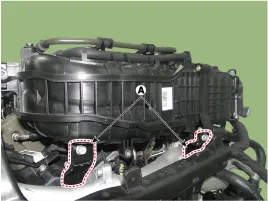
| 13. |
Remove the surge tank fixing bracket (A).
|
| 14. |
Remove the surge tank (A).
|

| 15. |
To install, reverse the removal procedure. |
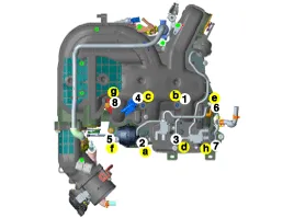
Components 1. Surge tank2. VIS actuator
Components 1. Intake manifold
Other information:
Hyundai Genesis (DH) 2013-2016 Service Manual: Blind Spot Detection Switch Repair procedures
Removal 1. Disconnect the negative (-) battery terminal. 2. Remove the crash pad lower panel. (Refer to Body - "Crash Pad") 3. Remove the blind spot detection (BSD) switch (A) after disengaging the mounting clip. Installation 1. Install the crash pad side switch assembly after connecting the connector.
Hyundai Genesis (DH) 2013-2016 Service Manual: PGS Unit (Back & Blinde Unit) Schematic Diagrams
C
Categories
- Manuals Home
- Hyundai Genesis Owners Manual
- Hyundai Genesis Service Manual
- Parking Assist Sensor Repair procedures
- Description and Operation
- Body (Interior and Exterior)
- New on site
- Most important about car

Copyright © 2026 www.hgenesisdh.com - 0.0238