Hyundai Genesis (DH): Brake System / Stop Signal Electronic Module Repair procedures
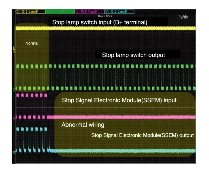
| Inspection |
| Removal |
| 1. |
Turn ignition switch OFF and disconnect the negative (-) battery cable. |
| 2. |
Remove the AVN unit.
(Refer to Body Electrical System - "AVN system" )
(Refer to Body Electrical System - "Premium AVN System") |
| 3. |
Remove the glove box.
(Refer to Body - "Glove Box" ) |
| 4. |
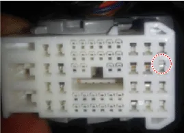
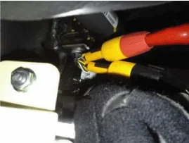
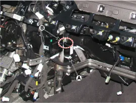
Disconnect the stop signal electronic module connector (A). |
| 5. |
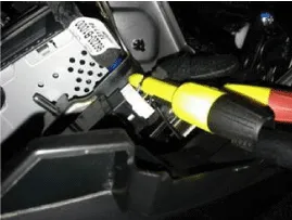
Remove the clip (B) and then remove the stop signal electronic module.
|
| 6. |
To install, reverse the removal procedure. |
System Circuit Diagram Terminal Function Description1Ground 2HAC/DBC Signal (Active Low)3ESS Signal (Active Low)4Stop lamp5Stop lamp switch6ECU/ SMK7ESS Signal (Active High)8Battery
Other information:
Hyundai Genesis (DH) 2013-2016 Service Manual: PGS Unit (Back & Blinde Unit) Repair procedures
Removal 1. Disconnect the negative (-) battery terminal. 2. Remove the glove box housing (A). (Refer to Body - "Glove Box") 3. Remove the PGS unit (A) after loosening the nuts. Installation 1. Install the PGS unit. 2. Install the glove box housing.
Hyundai Genesis (DH) 2013-2016 Service Manual: Auto Defogging Sensor Description and Operation
Description The auto defogging sensor is installed on the front window glass. The sensor judges and sends signal if moisture occurs to blow out wind for defogging. The air conditioner control module receives signal from the sensor and restrains moisture and eliminate defog by controlling the intake actuator, A/C, auto defogging actuator,
Categories
- Manuals Home
- Hyundai Genesis Owners Manual
- Hyundai Genesis Service Manual
- Description and Operation
- Engine Electrical System
- Parking Assist Sensor Repair procedures
- New on site
- Most important about car
