Hyundai Genesis (DH): ECS(Electronic Control Suspension) System / Schematic Diagrams
Hyundai Genesis (DH) 2013-2016 Service Manual / Suspension System / ECS(Electronic Control Suspension) System / Schematic Diagrams
| Schematic Diagrams |
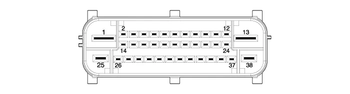
| 1. |
Connector input/output
|
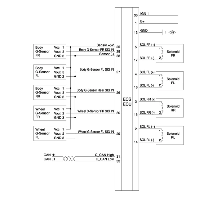
| 2. |
Circuit diagram
|
Description Real-time continuous control of the damping force according to vehicle running conditions and the state of road surface will enhance ride comfort and steering safety, including roll/pitch reduction in case of vehicle dynamics control, quick turning, braking, and starting.
Replacement 1. Disconnect the battery (-) terminal. 2. Remove the trunk luggage side trim [RH]. (Refer to Body - "Trunk Trim") 3. Disconnect the connector and then remove the ECS control unit.
Other information:
Hyundai Genesis (DH) 2013-2016 Service Manual: High Mounted Stop Lamp Repair procedures
Removal High Mounted Stop Lamp 1. Disconnect the negative (-) battery terminal. 2. Remove the roof trim assembly. (Refer to Body - "Roof Trim") 3. Remove the high mounted stop lamp assembly (A) after loosening the mounting screws. Installation 1.
Hyundai Genesis (DH) 2013-2016 Service Manual: Heater & A/C Control Unit Components and Components Location
C
Categories
- Manuals Home
- Hyundai Genesis Owners Manual
- Hyundai Genesis Service Manual
- Active Air Flap(AAF) Repair procedures
- Smart Cruise Control Unit Repair procedures
- Body Electrical System
- New on site
- Most important about car

Copyright © 2026 www.hgenesisdh.com - 0.0214