Hyundai Genesis (DH): ECS(Electronic Control Suspension) System / Description and Operation
| Description |


| Item | Shape | Function |
| body G-sensor |
| Body motion detection Sky hook damping control(pitch, bounce control) |
| Wheel G-sensor |
| Wheel roughness detection Damper velocity estimation |
| Vehicle Signals | Vehicle Speed Throttle position sensor Brake Steering Angle Drive mode switch signal | |
| Steering angle sensor |
| Estimation Of The Driver's Steering Left/Right acceleration measurements |


| Operation |
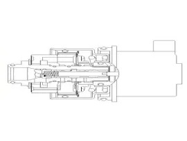
Components 1. ECU2. Front Continuously Variable Damper3. Wheel G-Sensors4. Rear Continuously Variable Damper5. Body G-Sensors Components Location ECS-ECU Body G-Sensors [Right Front] [Left Front] [Right Rear] Wheel G-Sensors [2EA] Front Continuously Variable Damper [2EA] Rear Continuously Variable Damper [2EA]
Schematic Diagrams 1. Connector input/output No.DescriptionPin No.Description1Battery(+)20-2Solenoid RL (+)21-3Solenoid RR (+)22-4Solenoid FL (+)23-5Solenoid FR (+)24-6- 25G- sensor power7- 26Body G-sensor signal RR8- 27Body G-sensor signal FL9- 28Wheel G-sensor signal FR10- 29Wheel G-sensor signal FL11- 30Wheel G-sensor signal FR12- 31CAN HIGH 13Ground32-14Solenoid RL (-) 33CAN LOW 15Solenoid RR (-)34-16Solenoid FL (-)35-17Solenoid FR (-)36IGN (+) 18-37-19-38G-Sensor Ground 2.
Other information:
Hyundai Genesis (DH) 2013-2016 Service Manual: Head Up Display Unit Repair procedures
Removal 1. Disconnect the negative (-) battery terminal. 2. Remove the head up display bezel (A). 3. Remove the instrument cluster. (Refer to Indicators And Guages - "Instrument Cluster") 4. Remove the head up display unit bracket (A) after loosening the mounting nuts.
Hyundai Genesis (DH) 2013-2016 Service Manual: Console Temperature Control Actuator Repair procedures
Inspection 1. Turn the ignition switch OFF. 2. Disconnect the console temperature control actuator connector. 3. Verify that the console temperature control actuator operates to the defrost mode when connecting 12V to terminal 3 and grounding terminal 4.
Categories
- Manuals Home
- Hyundai Genesis Owners Manual
- Hyundai Genesis Service Manual
- Steering System
- Heating, Ventilation and Air Conditioning
- Body (Interior and Exterior)
- New on site
- Most important about car
