
Hyundai Genesis (DH): ECS(Electronic Control Suspension) System / ECS Control Unit Repair procedures
| Replacement |
| 1. |
Disconnect the battery (-) terminal. |
| 2. |
Remove the trunk luggage side trim [RH].
(Refer to Body - "Trunk Trim") |
| 3. |
Disconnect the connector and then remove the ECS control unit.
|
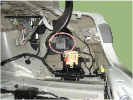
| Installation |
| 1. |
Installation in the reverse order of removal. |
| 2. |
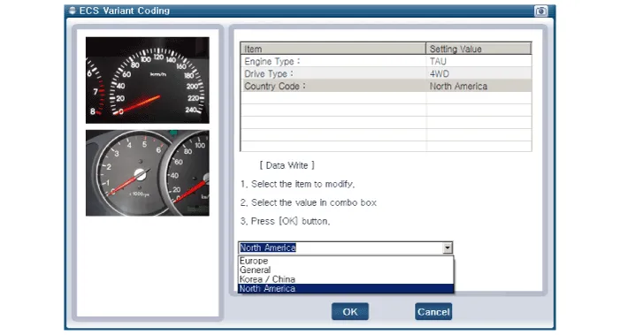
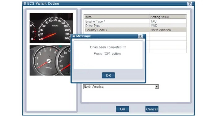
Perform the ESC variant coding.
|
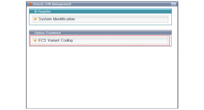
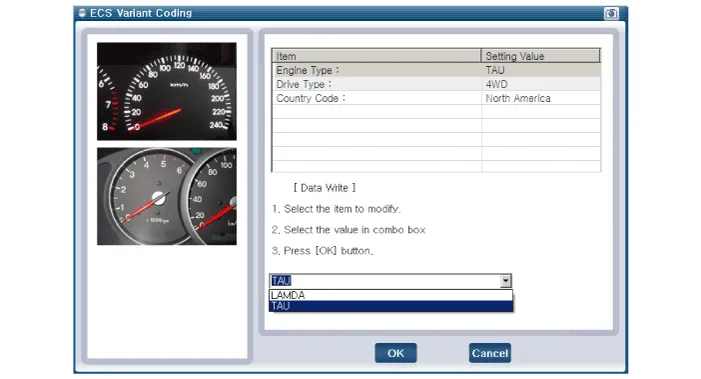
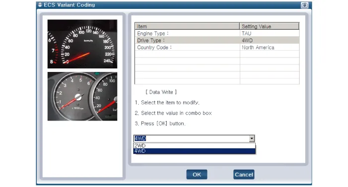
Schematic Diagrams 1. Connector input/output No.DescriptionPin No.Description1Battery(+)20-2Solenoid RL (+)21-3Solenoid RR (+)22-4Solenoid FL (+)23-5Solenoid FR (+)24-6- 25G- sensor power7- 26Body G-sensor signal RR8- 27Body G-sensor signal FL9- 28Wheel G-sensor signal FR10- 29Wheel G-sensor signal FL11- 30Wheel G-sensor signal FR12- 31CAN HIGH 13Ground32-14Solenoid RL (-) 33CAN LOW 15Solenoid RR (-)34-16Solenoid FL (-)35-17Solenoid FR (-)36IGN (+) 18-37-19-38G-Sensor Ground 2.
Replacement Front 1. Loosen the wheel nuts slightly. Raise the vehicle, and make sure it is securely supported. 2. Remove the front wheel and tire (A) from the front hub.
Other information:
Hyundai Genesis (DH) 2013-2016 Service Manual: Front Fog Lamps Repair procedures
Removal 1. Disconnect the negative (-) battery terminal. 2. Remove the front bumper. (Refer to Body - "Front Bumper Cover") 3. Disconnect the front fog lamp connector (A). 4. Remove the front fog lamp assembly (A) after loosening the mounting nut.
Hyundai Genesis (DH) 2013-2016 Service Manual: Components and Components Location
C
Categories
- Manuals Home
- Hyundai Genesis Owners Manual
- Hyundai Genesis Service Manual
- Restraint
- Description and Operation
- Transmission Control Module (TCM) Repair procedures
- New on site
- Most important about car
