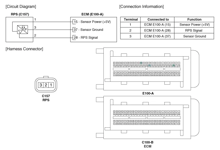
Hyundai Genesis (DH): Engine Control System / Rail Pressure Sensor (RPS) Schematic Diagrams
| Circuit Diagram |
Signal Waveform
Inspection 1. Connect the GDS on the Data Link Connector (DLC). 2. Measure the output voltage of the RPS at idle and various engine speed. ConditionOutput Voltage (V)Idle Approx.
Other information:
Hyundai Genesis (DH) 2013-2016 Service Manual: Temperature Control Actuator Repair procedures
Inspection 1. Turn the ignition switch OFF. 2. Disconnect the temperature control actuator connector. 3. Verify that the temperature control actuator operates to the warm (Driver's side) or cool (Passenger's side) position when connecting 12V to terminal 3 and grounding terminal 4.
Hyundai Genesis (DH) 2013-2016 Service Manual: Auto Defogging Actuator Repair procedures
Inspection 1. Turn the ignition switch OFF. 2. Disconnect the auto defogging connector. 3. Verify that the auto defogging actuator operates to the open position when connecting 12V to terminal 3 and grounding terminal 4. Verify that the auto defogging actuator operates to the close position when connected in reverse.
Categories
- Manuals Home
- Hyundai Genesis Owners Manual
- Hyundai Genesis Service Manual
- Electric Parking Brake (EPB) Repair procedures
- Active Air Flap(AAF) Repair procedures
- Starter Repair procedures
- New on site
- Most important about car
