Hyundai Genesis (DH): Premium AVN System / External AMP Repair procedures
| Removal |
| 1. |
Disconnect the negative (-) battery terminal. |
| 2. |
Open the trunk, remove the left trunk trim.
(Refer to Body - "Trunk Trim") |
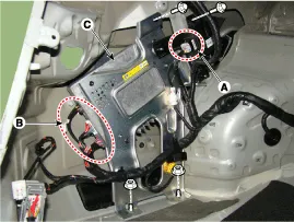
| 3. |
Remove the external amplifier (C) after disconnecting the connector (A),(B) and loosening the mounting nuts.
|
| Installation |
| 1. |
Install the external amplifier after connecting the connector. |
| 2. |
Install the left trunk trim. |
| 3. |
Connect the negative (-) battery terminal.
|

| Inspection |
| 1. |
In the body electrical system, failure can be quickly diagnosed by using the vehicle diagnostic system (GDS).
The diagnostic system(GDS) provides the following information.
|
| 2. |
Select the 'Car model' and the system to be checked in order to check the vehicle with the tester. |
| 3. |
Select the 'AVN' to check the AVN. |
| 4. |
Select the 'Current data" menu to search the current state of the input/output data.
The input/output data for the sensors corresponding to the AVN can be checked. |
| 5. |
To forcibly actuate the input value of the module to be checked, select option "Actuation test". |
Components NO.Connector ANO.Connector BNO.Connector C1-1GND1transmission (Tx)2Front center (-)2Front Left midrange/tweeter(+)2reception (Rx)3Front center (+)3Front Left midrange/tweeter(-)3?4Subwoofer (-)4Left Surround (+)45Subwoofer (+)5Left Surround (-)56-6-67-7-78Front bass(LH)(+)8-89Front bass(LH)(-)9-910Front bass(RH)(-)10-1011Front bass(RH)(+)11-1112-12B (+)1213left midrange/tweeter(-)13bass (LH) (-)1314left midrange/tweeter(+)14bass (LH) (+)1415ight midrange/tweeter(-)15Reserved (-)1516Right midrange/tweeter(+)16Reserved (+)1617bass (RH) (-)17-1718bass (RH) (+)18CAN (-)1819Front midrange/tweeter(+)19CAN (+)1920Front midrange/tweeter(-)20-2021Surround(RH) (-)21IGN12122Surround(RH) (+)22ACC22
Other information:
Hyundai Genesis (DH) 2013-2016 Service Manual: Start/Stop Button Repair procedures
Removal 1. Disconnect the negative(-) battery terminal. 2. Remove the driver crash pad lower panel. (Refer to Body - "Crash Pad Lower Panel") 3. Remove the start/stop button (A) from the center fascia garnish after loosening the mounting clip.
Hyundai Genesis (DH) 2013-2016 Service Manual: Description and Operation
Description Control Function This system supports 2 kinds of main function. (Rear video display function, Expected trace of wheels display function) The Rear video display and the expected trace of wheels display operate according to Vehicle speed condition and Gear position.
Categories
- Manuals Home
- Hyundai Genesis Owners Manual
- Hyundai Genesis Service Manual
- Starter Repair procedures
- Smart Cruise Control Unit Repair procedures
- Body (Interior and Exterior)
- New on site
- Most important about car
