Hyundai Genesis (DH): Premium AVN System / External AMP Components and Components Location
Hyundai Genesis (DH) 2013-2016 Service Manual / Body Electrical System / Premium AVN System / External AMP Components and Components Location
| Components |
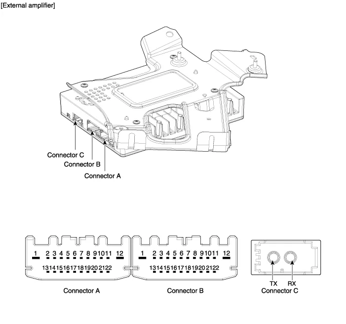
| NO. | Connector A | NO. | Connector B | NO. | Connector C |
| 1 | - | 1 | GND | 1 | transmission (Tx) |
| 2 | Front center (-) | 2 | Front Left midrange/tweeter(+) | 2 | reception (Rx) |
| 3 | Front center (+) | 3 | Front Left midrange/tweeter(-) | 3 | ? |
| 4 | Subwoofer (-) | 4 | Left Surround (+) | 4 | |
| 5 | Subwoofer (+) | 5 | Left Surround (-) | 5 | |
| 6 | - | 6 | - | 6 | |
| 7 | - | 7 | - | 7 | |
| 8 | Front bass(LH)(+) | 8 | - | 8 | |
| 9 | Front bass(LH)(-) | 9 | - | 9 | |
| 10 | Front bass(RH)(-) | 10 | - | 10 | |
| 11 | Front bass(RH)(+) | 11 | - | 11 | |
| 12 | - | 12 | B (+) | 12 | |
| 13 | left midrange/tweeter(-) | 13 | bass (LH) (-) | 13 | |
| 14 | left midrange/tweeter(+) | 14 | bass (LH) (+) | 14 | |
| 15 | ight midrange/tweeter(-) | 15 | Reserved (-) | 15 | |
| 16 | Right midrange/tweeter(+) | 16 | Reserved (+) | 16 | |
| 17 | bass (RH) (-) | 17 | - | 17 | |
| 18 | bass (RH) (+) | 18 | CAN (-) | 18 | |
| 19 | Front midrange/tweeter(+) | 19 | CAN (+) | 19 | |
| 20 | Front midrange/tweeter(-) | 20 | - | 20 | |
| 21 | Surround(RH) (-) | 21 | IGN1 | 21 | |
| 22 | Surround(RH) (+) | 22 | ACC | 22 |
Removal Take care not to scratch the crash pad and related parts. 1. Disconnect the negative (-) battery terminal. 2. Remove the crash pad side garnish assembly.
Removal 1. Disconnect the negative (-) battery terminal. 2. Open the trunk, remove the left trunk trim. (Refer to Body - "Trunk Trim") 3. Remove the external amplifier (C) after disconnecting the connector (A),(B) and loosening the mounting nuts.
Other information:
Hyundai Genesis (DH) 2013-2016 Service Manual: Rheostat Repair procedures
Inspection 1. Disconnect the negative (-) battery terminal. 2. Remove the crash pad lower panel. (Refer to Body - "Crash Pad Lower Panel") 3. Remove the lower crash pad switch assembly (A) after disengaging the mounting clip. 4. Remove the rheostat switch connector (A).
Hyundai Genesis (DH) 2013-2016 Service Manual: Components and Components Location
C
Categories
- Manuals Home
- Hyundai Genesis Owners Manual
- Hyundai Genesis Service Manual
- Parking Assist Sensor Repair procedures
- Description and Operation
- Body (Interior and Exterior)
- New on site
- Most important about car

Copyright © 2026 www.hgenesisdh.com - 0.0208