Hyundai Genesis (DH): Premium AVN System / Front LCD monitor Repair procedures
| Removal |
Take care not to scratch the crash pad and related parts. |

| 1. |
Disconnect the negative (-) battery terminal. |
| 2. |
Remove the crash pad side garnish assembly.
(Refer to Body - "Crash pad side garnish assembly")
|
| 3. |
Remove the fascia panel monitor.
(Refer to Body - "Crash Pad Main Lower Assembly") |
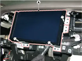
| 4. |
Remove the front LCD monitor after loosening the mounting screws.
|
| Installation |
| 1. |
Install the front LCD monitor after connecting the connector. |
| 2. |
Install the monitor fascia panel.
|
Components NO.Connector ANO.Connector BNO.Connector C1-1GND1transmission (Tx)2Front center (-)2Front Left midrange/tweeter(+)2reception (Rx)3Front center (+)3Front Left midrange/tweeter(-)3?4Subwoofer (-)4Left Surround (+)45Subwoofer (+)5Left Surround (-)56-6-67-7-78Front bass(LH)(+)8-89Front bass(LH)(-)9-910Front bass(RH)(-)10-1011Front bass(RH)(+)11-1112-12B (+)1213left midrange/tweeter(-)13bass (LH) (-)1314left midrange/tweeter(+)14bass (LH) (+)1415ight midrange/tweeter(-)15Reserved (-)1516Right midrange/tweeter(+)16Reserved (+)1617bass (RH) (-)17-1718bass (RH) (+)18CAN (-)1819Front midrange/tweeter(+)19CAN (+)1920Front midrange/tweeter(-)20-2021Surround(RH) (-)21IGN12122Surround(RH) (+)22ACC22
Other information:
Hyundai Genesis (DH) 2013-2016 Service Manual: Auto Light Sensor Components and Components Location
C
Hyundai Genesis (DH) 2013-2016 Service Manual: Compressor Repair procedures
Removal 1. If the compressor is marginally operable, run the engine at idle speed, and let the air conditioning work for a few minutes, then shut the engine off. 2. Disconnect the negative (-) battery terminal. 3. Remove the engine room cover.
Categories
- Manuals Home
- Hyundai Genesis Owners Manual
- Hyundai Genesis Service Manual
- Electric Parking Brake (EPB) Repair procedures
- Starter Repair procedures
- Engine Electrical System
- New on site
- Most important about car
