Hyundai Genesis (DH): Lighting System / Door Mirror Lamp Repair procedures
Hyundai Genesis (DH) 2013-2016 Service Manual / Body Electrical System / Lighting System / Door Mirror Lamp Repair procedures
| Removal |
Puddle Lamp
| 1. |
Disconnect the negative (-) battery terminal. |
| 2. |
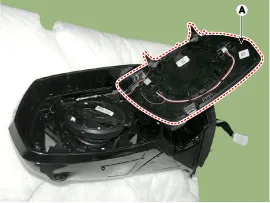
Remove the mirror holder (A) from the outside mirror assembly.
|

| 3. |
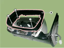
Remove the door mirror housing (A) after loosening a screw.
|
| 4. |
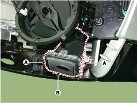
Remove the puddle lamp (B) after disengaging the mounting clip.
|
| 5. |
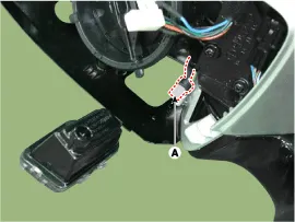
Disconnect the puddle lamp connector (A).
|
| Installation |
Puddle Lamp
| 1. |
Install the puddle lamp. |
| 2. |
Install the door mirror cover and housing. |
| 3. |
Install the door mirror. |
| 4. |
Connect the negative (-) battery terminal. |
Inspection 1. Check the battery voltage. (Low beam will be on when the battery voltage above 9V.) 2. Check the fuse and relay. 3. Check the ballast power supply terminals (if the terminals are reversed, the low beam does not illuminate.
Removal 1. Disconnect the negative (-) battery terminal. 2. Separate the room lamp (B) from the roof trim after disengaging the mounting clip (A).
Categories
- Manuals Home
- Hyundai Genesis Owners Manual
- Hyundai Genesis Service Manual
- Restraint
- Electric Parking Brake (EPB) Repair procedures
- Suspension System
- New on site
- Most important about car

Copyright © 2026 www.hgenesisdh.com - 0.0184