Hyundai Genesis (DH): Autonomous Emergency Braking(AEB) System / Description and Operation
Hyundai Genesis (DH) 2013-2016 Service Manual / Brake System / Autonomous Emergency Braking(AEB) System / Description and Operation
| Description |
AEB(Autonomous Emergency Braking) is a function purposed to
avoid the collision or to reduce the damage against the accident which
can be taken place from the late braking or insufficient braking power
due to the reason of absented mind of the driver.
The sequence of system control is as follows.
| 1. |
Sensing the vehicle driving ahead and data analysis with the
radar sensor of smart cruise control system (SCC) and camera sensor on
the Lane Keeping Assist System (LKAS) (CAN Communication) |
| 2. |
Checking the vehicle for AEB control with analyzed sensing data |
| 3. |
Calculation of proper speed reduction depending on the existence/speed/distance of the car ahead |
| 4. |
Transmitting the calculated "required speed reduction" to the Electronic Stability Control(ESC) (CAN Communication) |
| 5. |
ESC performs the braking control after calculating the
required torque for realizing the "required speed reduction" (CAN
Communication) |
| Operation |
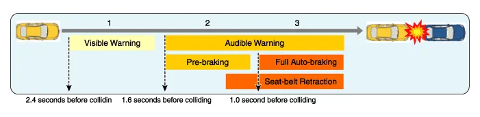
? The time presented in the illustration varies depending on the vehicle speed.
| |
Components components and components location AEB system consists of the following systems Device to detect a potential obstacle forward (radar, cameras) Human-Machine Interface (HMI) to warn the driver and change settings Braking device for generating a braking force
Other information:
Hyundai Genesis (DH) 2013-2016 Service Manual: Front Fog Lamps Repair procedures
Removal 1. Disconnect the negative (-) battery terminal. 2. Remove the front bumper. (Refer to Body - "Front Bumper Cover") 3. Disconnect the front fog lamp connector (A). 4. Remove the front fog lamp assembly (A) after loosening the mounting nut.
Hyundai Genesis (DH) 2013-2016 Service Manual: Auto Light Sensor Components and Components Location
C
Categories
- Manuals Home
- Hyundai Genesis Owners Manual
- Hyundai Genesis Service Manual
- Suspension System
- General Information
- Steering System
- New on site
- Most important about car

Copyright © 2026 www.hgenesisdh.com - 0.0277