Hyundai Genesis (DH): General Information / Description and Operation
| Description |
| 1. |
Description
 Distribution of electronically controlled driving force Distribution of electronically controlled driving force
 Mutual controlling with the related driving control system Mutual controlling with the related driving control system
|
| 2. |
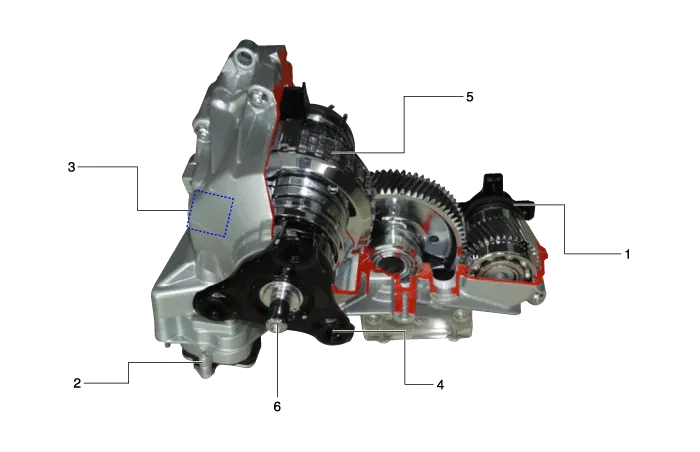
Structure of transfer case
|
| 3. |
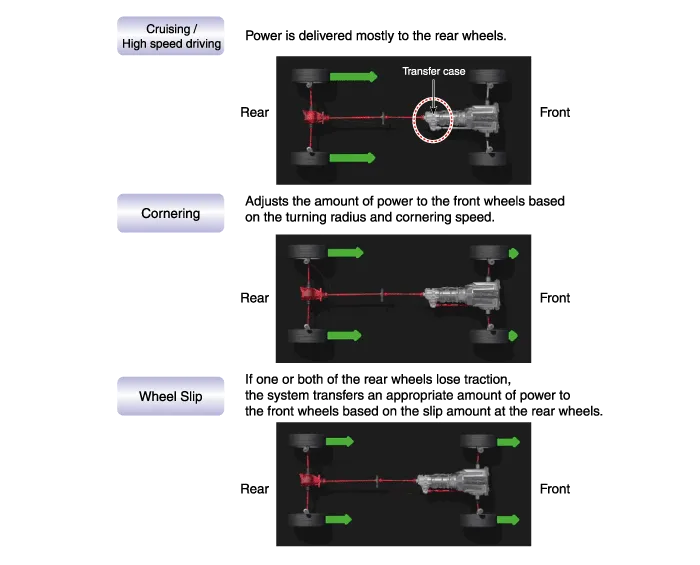
Outline of driving force distribution
|
| 4. |
Transfer case operation
1) Transfer case operation procedure
? ITA (Integrated Transfer case Actuator)
|
 Operation of Ball ramp with worm gear
 Clutch operation with Ball ramp operation
 Transmitting of torque to the gear with clutch operation
 Applying the driving force to the front wheel
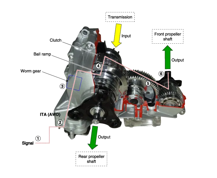
Specification ItemSpecificationProduct nameTransfer caseOperation methodElectronic actuator control method (BLDC motor)Torque capacity1,100 NmWeight25 kg (Oil injection state) Tightening Torques Item N.
Adjustment Introduction It is necessary to check and input the calibration data when the controller is replaced as the characteristics of the internal frictional materials (clutch pack) change due to driving.
Other information:
Hyundai Genesis (DH) 2013-2016 Service Manual: Photo Sensor Description and Operation
Description The photo sensor is located in the right side of the inside rearview mirror. he integrated rain sensor is located in the right side of the inside rearview mirror. The integrated rain sensor is a multifunctional sensor which combines the photo sensor and auto light sensor, and has a built-in photovoltaic diode (for detecting t
Hyundai Genesis (DH) 2013-2016 Service Manual: Heater & A/C Control Unit Repair procedures
Self Diagnosis 1. Self-diagnosis process 2. How to read self-diagnostic code After the display panel blinks three times every 0.5 second, the corresponding fault code blinks on the setup temperature display panel every 0.5 second and will show two figures.
Categories
- Manuals Home
- Hyundai Genesis Owners Manual
- Hyundai Genesis Service Manual
- Brake System
- Repair procedures
- Starter Repair procedures
- New on site
- Most important about car
