Hyundai Genesis (DH): Blind Spot Detection system / Blind Spot Detection Switch Components and Components Location
Hyundai Genesis (DH) 2013-2016 Service Manual / Body Electrical System / Blind Spot Detection system / Blind Spot Detection Switch Components and Components Location
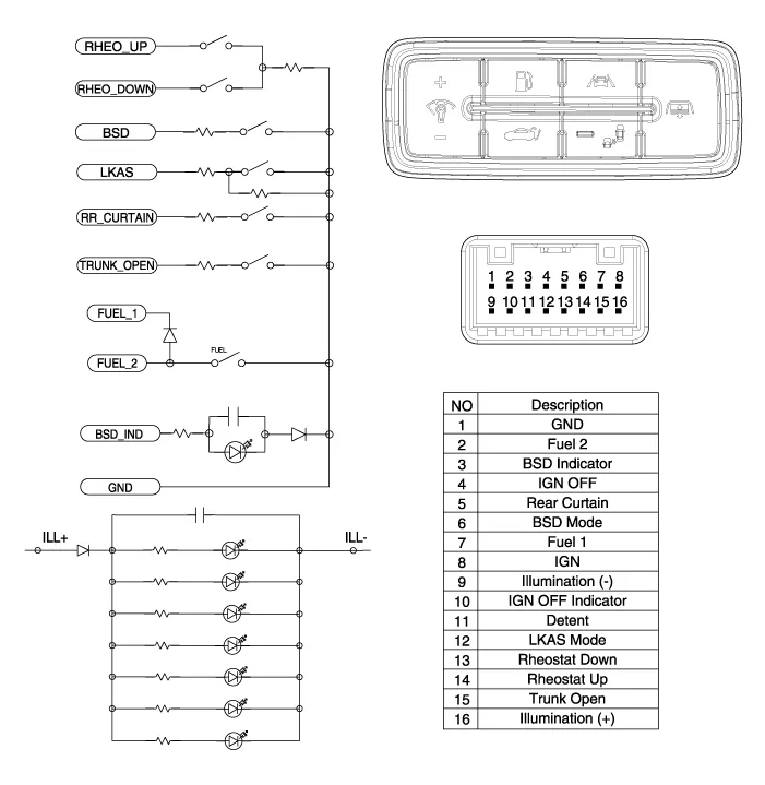
| Circuit Diagram |
Removal 1. Disconnect the negative (-) battery terminal. 2. Remove the rear bumper. (Refer to Body - "Rear Bumper") 3. Remove the BSD unit (A) after loosening the mounting nuts.
Removal 1. Disconnect the negative (-) battery terminal. 2. Remove the crash pad lower panel. (Refer to Body - "Crash Pad") 3. Remove the blind spot detection (BSD) switch (A) after disengaging the mounting clip.
Categories
- Manuals Home
- Hyundai Genesis Owners Manual
- Hyundai Genesis Service Manual
- Description and Operation
- Transmission Control Module (TCM) Repair procedures
- Repair procedures
- New on site
- Most important about car

Copyright © 2026 www.hgenesisdh.com - 0.028