Hyundai Genesis (DH): Brake System / Stop Signal Electronic Module Schematic Diagrams
Hyundai Genesis (DH) 2013-2016 Service Manual / Brake System / Brake System / Stop Signal Electronic Module Schematic Diagrams
| System Circuit Diagram |
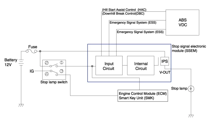
| Terminal Function |
| Description | |
| 1 | Ground |
| 2 | HAC/DBC Signal (Active Low) |
| 3 | ESS Signal (Active Low) |
| 4 | Stop lamp |
| 5 | Stop lamp switch |
| 6 | ECU/ SMK |
| 7 | ESS Signal (Active High) |
| 8 | Battery |
Specifications CategoryDataOperation temperature range (
Inspection 1. Fuse inspection Install the test fuse to the switch fuse and relay fuse part in order to confirm a normal joint fit. 2. Inspection of connector by each part Check whether each connector is damaged, or there is terminal surge or incomplete connection.
Other information:
Hyundai Genesis (DH) 2013-2016 Service Manual: Specifications
S
Hyundai Genesis (DH) 2013-2016 Service Manual: Parking Assist Sensor Repair procedures
Removal 1. Disconnect the negative (-) battery terminal. 2. Remove the front/rear bumper cover. (Refer to Body - "Front Bumper Cover") (Refer to Body - "Rear Bumper Cover") 3. Disconnect the connector (B) from the parking assist sensor (A).
Categories
- Manuals Home
- Hyundai Genesis Owners Manual
- Hyundai Genesis Service Manual
- Starter Repair procedures
- Engine Mechanical System
- Body Electrical System
- New on site
- Most important about car

Copyright © 2026 www.hgenesisdh.com - 0.0242