Hyundai Genesis (DH): General Information / Schematic Diagrams
Hyundai Genesis (DH) 2013-2016 Service Manual / Emission Control System / General Information / Schematic Diagrams
| Schematic Diagram |
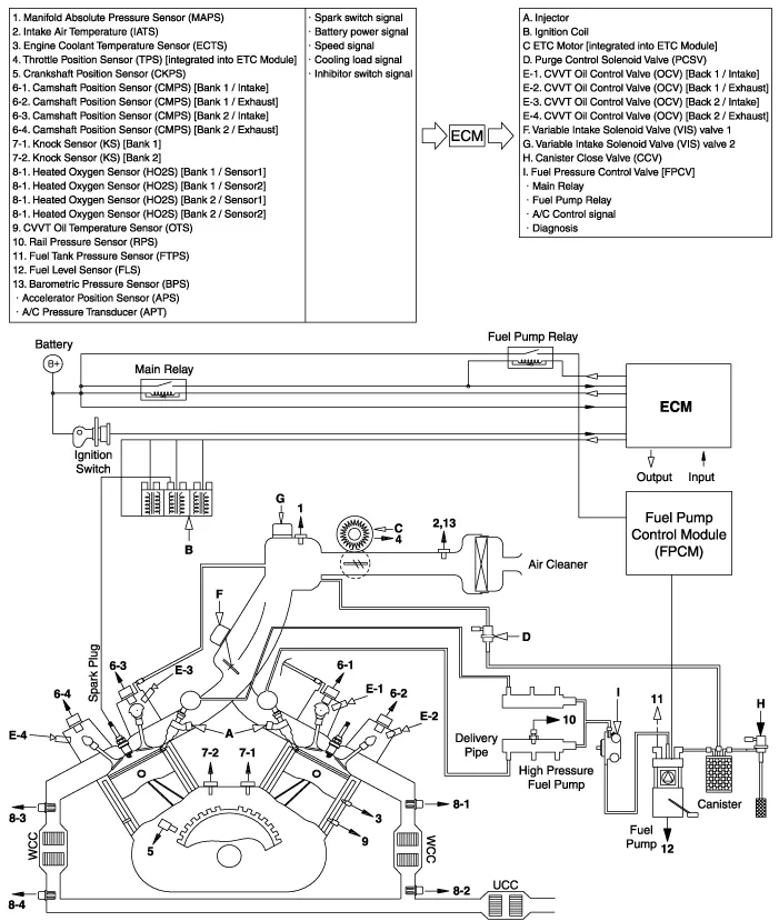
Components Location 1. PCV Valve2. Canister3. Purge Control Solenoid Valve (PCSV)4. Fuel Tank Pressure Sensor (FTPS)5. Canister Close Valve (CCV)6.
Other information:
Hyundai Genesis (DH) 2013-2016 Service Manual: Components and Components Location
C
Hyundai Genesis (DH) 2013-2016 Service Manual: Blind Spot Detection Unit Repair procedures
Removal 1. Disconnect the negative (-) battery terminal. 2. Remove the rear bumper. (Refer to Body - "Rear Bumper") 3. Remove the BSD unit (A) after loosening the mounting nuts. Take care not to separate the bracket from rear bumper when removing the BSD sensor.
Categories
- Manuals Home
- Hyundai Genesis Owners Manual
- Hyundai Genesis Service Manual
- 4 Wheel Drive (AWD) System
- Starter Repair procedures
- Suspension System
- New on site
- Most important about car

Copyright © 2026 www.hgenesisdh.com - 0.0333