Hyundai Genesis (DH): Lighting System / Rheostat Components and Components Location
| Components |
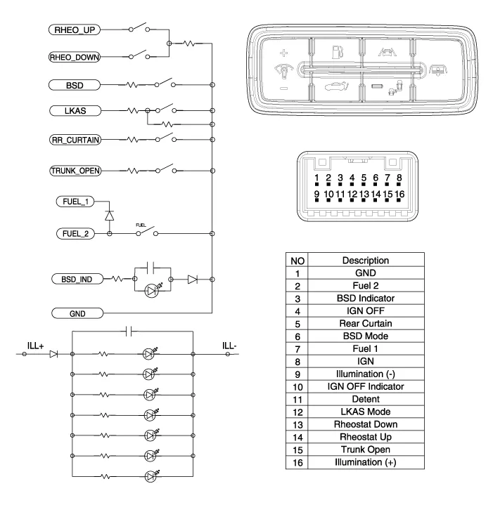
Inspection 1. Check for continuity between terminals. If the continuity is not as specified, replace the hazard lamp switch. No.Description1BAT (+)2Illumination (+)3-4Signal5Pilot lamp6-7Illumination (-)8GND Removal
Inspection 1. Disconnect the negative (-) battery terminal. 2. Remove the crash pad lower panel. (Refer to Body - "Crash Pad Lower Panel") 3.
Other information:
Hyundai Genesis (DH) 2013-2016 Service Manual: Blind Spot Detection Indicator Repair procedures
Removal Blind Spot Detection Warning Indicator 1. Disconnect the negative (-) battery terminal. 2. Remove the mirror (A). Installation Blind Spot Detection Warning Indicator 1. Install the outside mirror. 2. Connect the negative (-) battery terminal.
Hyundai Genesis (DH) 2013-2016 Service Manual: Compressor oil Repair procedures
Oil Specification 1. The HFC-134a system requires synthetic (PAG) compressor oil whereas the R-12 system requires mineral compressor oil. The two oils must never be mixed. 2. Compressor (PAG) oil varies according to compressor model. Be sure to use oil specified for the compressor model.
Categories
- Manuals Home
- Hyundai Genesis Owners Manual
- Hyundai Genesis Service Manual
- Brake System
- Smart Cruise Control Unit Repair procedures
- Description and Operation
- New on site
- Most important about car
