Hyundai Genesis (DH): Motor Driven Power Steering / Steering Gear box Repair procedures
Hyundai Genesis (DH) 2013-2016 Service Manual / Steering System / Motor Driven Power Steering / Steering Gear box Repair procedures
| Replacement |
| [LHD] |
| 1. |
Loosen the wheel nuts slightly. Raise the vehicle, and make sure it is securely supported. |
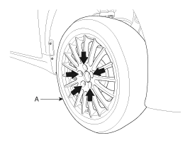
| 2. |
Remove the front wheel and tire (A) from the front hub.
|

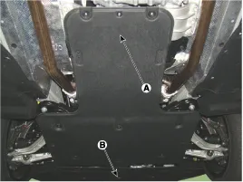
| 3. |
Remove the under cover (A), (B).
|
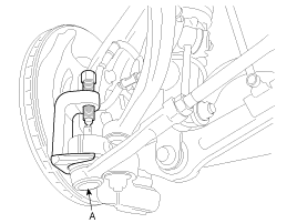
| 4. |
Remove the tie rod end ball joint from the knuckle.
|
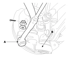
| 5. |
Unscrew the steering column bolt (A) to disconnect the universal joint and steering gear connection.
|

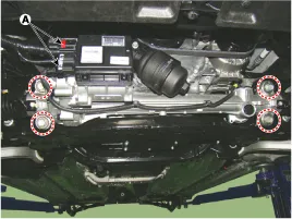
| 6. |
Disconnect the connector (A) and then loosen the gear box mounting bolts.
[4WD]
[2WD]
|

| [RHD] |
| 1. |
Loosen the wheel nuts slightly. Raise the vehicle, and make sure it is securely supported. |
| 2. |
Remove the front wheel and tire (A) from the front hub.
|
| 3. |
Remove the under cover (A), (B).
|
| 4. |
Remove the tie rod end ball joint from the knuckle.
|
| 5. |
Unscrew the steering column bolt (A) to disconnect the universal joint and steering gear connection.
|

| 6. |
Disconnect the connector (A).
|

| 7. |
Loosen the gear box mounting bolts.
|

| Installation |
| 1. |
Install in the reverse order of removal. |
| 2. |
Check the alignment.
(Refer to Suspension System - "Alignment") |
EPS Specification Recognition
Precautions when performing the EPS specification recognition procedure:
| |
Components Location [4WD] 1. Steering gear box2. Motor3. ECU4. Sub frame5. Knuckle [2WD] 1. Steering gear box2. Motor3. ECU4. Sub frame
Other information:
Hyundai Genesis (DH) 2013-2016 Service Manual: Auto Head Lamp Leveling Unit Description and Operation
Description According to driving environment and loading state of vehicle, head lamp lighting direction is changed to keep the driver's visibility range and to protect the driver's vision from glare, aiming at safety driving. Sensor integrated ECU mounting on the rear center arm drives the actuator mounting on the head lamp since sens
Hyundai Genesis (DH) 2013-2016 Service Manual: Parking Assist Sensor Repair procedures
Removal 1. Disconnect the negative (-) battery terminal. 2. Remove the front/rear bumper cover. (Refer to Body - "Front Bumper Cover") (Refer to Body - "Rear Bumper Cover") 3. Disconnect the connector (B) from the parking assist sensor (A).
Categories
- Manuals Home
- Hyundai Genesis Owners Manual
- Hyundai Genesis Service Manual
- Steering System
- Emission Control System
- 4 Wheel Drive (AWD) System
- New on site
- Most important about car

Copyright © 2026 www.hgenesisdh.com - 0.0197