Hyundai Genesis (DH): Cruise Control System / Troubleshooting
| Trouble Symptom Charts |
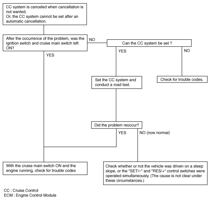
| Trouble Symptom 1 |
| Trouble Symptom 2 |
| Trouble symptom | Probable cause | Remedy |
| The set vehicle speed turns too high or low. "Surging" (repeated alternating acceleration and deceleration) occurs after setting | Malfunction of the vehicle speed sensor circuit | Repair the vehicle speed sensor system, or replace the part |
| Malfunction of ECM | Check input and output signals at ECM |
| Trouble Symptom 3 |
| Trouble symptom | Probable cause | Remedy |
| The CC system is not canceled when the brake pedal is depressed | Damaged or disconnected wiring of the brake pedal switch | Repair the harness or replace the brake pedal switch |
| Malfunction of the ECM signals | Check input and output signals at ECM |
| Trouble Symptom 4 |
| Trouble symptom | Probable cause | Remedy |
| The CC system is not canceled when the shift lever moves to the
"N" position (It is canceled, however, when the brake pedal is
depressed) | Damaged or disconnected wiring of inhibitor switch input circuit | Repair the harness, or repair or replace the inhibitor switch |
| Improper adjustment of inhibitor switch |
| Malfunction of the ECM signals | Check input and output signals at ECM |
| Trouble Symptom 5 |
| Trouble symptom | Probable cause | Remedy |
| Cannot decelerate (coast) by using the "SET/ |
System Block Diagram Component Parts And Function Outline Component partFunctionVehicle-speed sensor, ESP/ABS Control ModuleConverts vehicle speed to pulse.
Circuit Diagram
Other information:
Hyundai Genesis (DH) 2013-2016 Service Manual: Auto Head Lamp Leveling Unit Troubleshooting
Inspection with GDS Initialization and diagnosis sequence by using GDS equipment. The following is the summarized A/S procedure. NoProcedure1Park the vehicle on level ground2Tire check3IGN1 ON4Head lamp Low Beam ON5Connection with diagnostic tool6Initial command by diagnostic tool7Clear DTC Code8IGN1 OFF > ON9Re- Connection with diagnostic t
Hyundai Genesis (DH) 2013-2016 Service Manual: Blind Spot Detection Unit Repair procedures
Removal 1. Disconnect the negative (-) battery terminal. 2. Remove the rear bumper. (Refer to Body - "Rear Bumper") 3. Remove the BSD unit (A) after loosening the mounting nuts. Take care not to separate the bracket from rear bumper when removing the BSD sensor.
Categories
- Manuals Home
- Hyundai Genesis Owners Manual
- Hyundai Genesis Service Manual
- Emission Control System
- Electric Parking Brake (EPB) Repair procedures
- Engine Mechanical System
- New on site
- Most important about car
