Hyundai Genesis (DH): Brake System / Rear Disc Brake Repair procedures
Hyundai Genesis (DH) 2013-2016 Service Manual / Brake System / Brake System / Rear Disc Brake Repair procedures
| Removal |
| 1. |
Remove the rear wheel & tire.
|
| 2. |
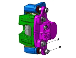
Loosen the guide rod bolt (B) and pivot the caliper up out of the way.
|

| 3. |
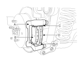
Remove pad shim (B), pad retainers (C) and brake pads (B) in the caliper bracket (A).
|
| 4. |
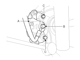
Loosen the hose eyebolt (B) and caliper mounting bolts (C), then remove the rear caliper assembly (A).
|
| 5. |
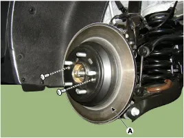
Remove the rear brake disc (A) by loosening the screws.
|
| Replacement |
| 1. |
Loosen the guide rod bolt (B) and pivot the caliper up out of the way.
|
| 2. |
Replace pad shim (B), pad retainers (C) and brake pads (B) in the caliper bracket (A).
|
| Inspection |
Rear Brake Disc Thickness Check
| 1. |
Check the brake pads for wear and fade. |
| 2. |
Check the brake disc for damage and cracks. |
| 3. |
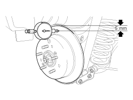
Remove all rust and contaminating materials from the surface,
and measure the disc thickness at the place of 5mm from the outer
circumference as the illustration below.
If wear exceeds the limit, replace the discs and pad assembly on the left and right of the vehicle. |
Rear Brake Pad Check
| 1. |
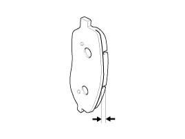
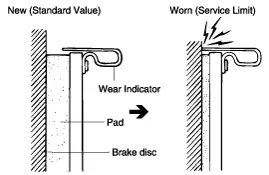
Check the pad wear. Measure the pad thickness and replace it, if it is less than the specified value.
|
| 2. |
Check that grease is applied to sliding contact points, and check the pad and backing metal for damage.
|

Rear Brake Disc Runout Check
| 1. |
Place a dial gauge about 5mm (0.2 in.) from the outer circumference of the brake disc, and measure the runout of the disc.
|
| 2. |
If the runout of the brake disc exceeds the limit specification, replace the disc, and then measure the runout again. |
| 3. |
If the runout exceeds the limit specification, install the
brake disc after turning it 180 |
Components 1. Guide rod bolt2. Bleed screw3. Caliper body4. Caliper carrier5. Inner pad shim6. Brake pad7. Pad retainer
Components Location 1. Brake pedal member assembly2. Stop lamp switch3. Clevis pin4. Snap pin5. Brake pedal stopper6. Return spring7. Bolt
Other information:
Hyundai Genesis (DH) 2013-2016 Service Manual: Components and Components Location
C
Hyundai Genesis (DH) 2013-2016 Service Manual: Heater Unit Components and Components Location
Component Location Components (1) 1. Shower duct (Left)2. Mode actuator (LH)3. Temperature control actuator (LH)4. Temperature door lever (Left)5. Mode actuator (A)6. Console temperature actuator (A)7. Console mode actuator ON/OFF8. Heater case (Left)9.
Categories
- Manuals Home
- Hyundai Genesis Owners Manual
- Hyundai Genesis Service Manual
- Smart Cruise Control Unit Repair procedures
- Description and Operation
- Steering System
- New on site
- Most important about car

Copyright © 2026 www.hgenesisdh.com - 0.0253