Hyundai Genesis (DH): Rear Suspension System / Rear Assist Arm Repair procedures
| Removal |
| 1. |
Loosen the wheel nuts slightly. Raise the vehicle, and make sure it is securely supported. |
| 2. |
Remove the front wheel and tire (A) from the rear hub.
|


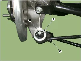
| 3. |
Remove the split pin (A) and nut (B).And using SST (09568-2J100), separate the assist arm (C).
|

| 4. |
Disconnect the rear assist arm (B) from the rear sub frame by loosening the bolt & nut (A).
|

| 5. |
Installation in the reverse order of removal. |
| 6. |
Check the alignment.
(Refer to Tires/Wheels - "Alignment") |
| Inspection |
| 1. |
Check the bushing for wear and deterioration. |
| 2. |
Check the ball joint for rotating torque. |
| 3. |
Check the assist arm for deformation. |
Removal 1. Loosen the wheel nuts slightly. Raise the vehicle, and make sure it is securely supported. 2. Remove the front wheel and tire (A) from the rear hub.
Removal 1. Loosen the wheel nuts slightly. Raise the vehicle, and make sure it is securely supported. 2. Remove the front wheel and tire (A) from the rear hub.
Other information:
Hyundai Genesis (DH) 2013-2016 Service Manual: Rheostat Repair procedures
Inspection 1. Disconnect the negative (-) battery terminal. 2. Remove the crash pad lower panel. (Refer to Body - "Crash Pad Lower Panel") 3. Remove the lower crash pad switch assembly (A) after disengaging the mounting clip. 4. Remove the rheostat switch connector (A).
Hyundai Genesis (DH) 2013-2016 Service Manual: Compressor oil Repair procedures
Oil Specification 1. The HFC-134a system requires synthetic (PAG) compressor oil whereas the R-12 system requires mineral compressor oil. The two oils must never be mixed. 2. Compressor (PAG) oil varies according to compressor model. Be sure to use oil specified for the compressor model.
Categories
- Manuals Home
- Hyundai Genesis Owners Manual
- Hyundai Genesis Service Manual
- Electric Parking Brake (EPB) Repair procedures
- Heating, Ventilation and Air Conditioning
- Repair procedures
- New on site
- Most important about car
