Hyundai Genesis (DH): Rear Suspension System / Rear Upper Arm Repair procedures
Hyundai Genesis (DH) 2013-2016 Service Manual / Suspension System / Rear Suspension System / Rear Upper Arm Repair procedures
| Removal |
| 1. |
Loosen the wheel nuts slightly. Raise the vehicle, and make sure it is securely supported. |
| 2. |
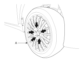
Remove the front wheel and tire (A) from the rear hub.
|

| 3. |
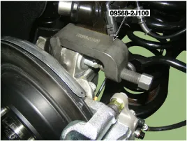
Support the lower portion of the rear axle with a jack securely. |
| 4. |
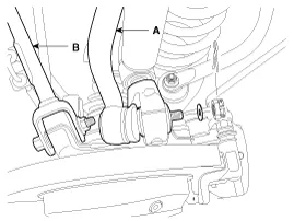
Loosen the mounting bolts and then remove the rear upper arm front (B) & rear upper arm rear (A).
|
| 5. |
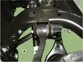
Loosen the flange bolt & nuts and then rear upper rear arm (A).
|
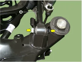
| 6. |
Loosen the flange bolt & nuts (A) and then rear upper front arm.
|
| 7. |
Installation in the reverse order of removal. |
| 8. |
Check the alignment.
(Refer to Tires/Wheels - "Alignment") |
| Inspection |
| 1. |
Check the bushing for wear and deterioration. |
| 2. |
Check the ball joint for rotating torque. |
Removal 1. Loosen the wheel nuts slightly. Raise the vehicle, and make sure it is securely supported. 2. Remove the front wheel and tire (A) from the rear hub.
Removal 1. Loosen the wheel nuts slightly. Raise the vehicle, and make sure it is securely supported. 2. Remove the front wheel and tire (A) from the rear hub.
Categories
- Manuals Home
- Hyundai Genesis Owners Manual
- Hyundai Genesis Service Manual
- Brake System
- Repair procedures
- Suspension System
- New on site
- Most important about car

Copyright © 2026 www.hgenesisdh.com - 0.0199