Hyundai Genesis (DH): Power Trunk Module / Power Trunk Module Drive Unit Repair procedures
Hyundai Genesis (DH) 2013-2016 Service Manual / Body Electrical System / Power Trunk Module / Power Trunk Module Drive Unit Repair procedures
| Removal |
|

| 1. |
Disconnect the negative (-) battery terminal. |
| 2. |
Remove the left trunk trim after opening the trunk.
(Refer to Body - "Trunk Trim") |
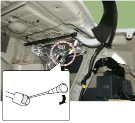
| 3. |
Separate the power trunk module push rod pin (A) and then remove the power trunk module connecting rod (B).
|
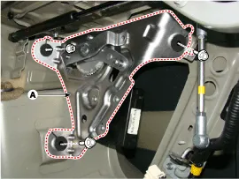
| 4. |
Remove the power trunk module & drive unit (A) after disconnecting the connector, bolts and nuts.
|
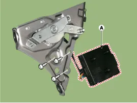
| 5. |
Remove the power trunk module (A) after loosening the mounting screws.
|
| Installation |
| 1. |
Tighten the power trunk module & drive unit mounting bolts and nuts.
|
| 2. |
Install the push rod in the hinge ball joint. |
| 3. |
Connect the control unit connectors. |
| 4. |
Install the right trunk trim. |
| 5. |
Check that the power trunk operates normally after connecting the negative (-) battery terminal.
|

| Inspection |
| 1. |
Disconnect the negative (-) battery terminal. |
| 2. |
Remove the left trunk trim.
(Refer to Body - "Trunk Trim") |
| 3. |
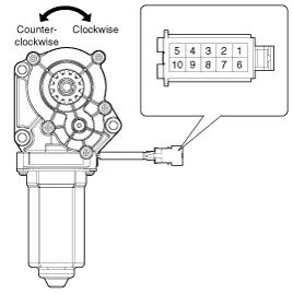
Remove the motor connector. |
| 4. |
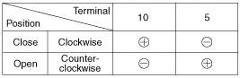
Connect the motor terminals directly to battery voltage (12V)
and check that the motor operates smoothly. Next, reverse the polarity
and check that the motor operates smoothly in the reverse direction. If
the operation is abnormal, replace the motor.
|
Description 1. Power trunk drive unit(Trunk open) A. The trunk open switch operates. (Trunk outside handle switch, Crash pad switch, SMK trunk open button) B.
Other information:
Hyundai Genesis (DH) 2013-2016 Service Manual: Refrigerant Line Repair procedures
Replacement 1. Discharge refrigerant from refrigeration system. 2. Replace any faulty tubes or hoses. Cap the open fittings immediately to keep moisture or dirt out of the system. 3. Tighten the bolt or nut joint to the specified torque.
Hyundai Genesis (DH) 2013-2016 Service Manual: Heater & A/C Control Unit Components and Components Location
C
Categories
- Manuals Home
- Hyundai Genesis Owners Manual
- Hyundai Genesis Service Manual
- Steering System
- Repair procedures
- Heating, Ventilation and Air Conditioning
- New on site
- Most important about car

Copyright © 2026 www.hgenesisdh.com - 0.0348