Hyundai Genesis (DH): Power Trunk Module / Power Trunk Inner Switch Repair procedures
Hyundai Genesis (DH) 2013-2016 Service Manual / Body Electrical System / Power Trunk Module / Power Trunk Inner Switch Repair procedures
| Inspection |
| 1. |
Remove the trunk inner switch. |
| 2. |
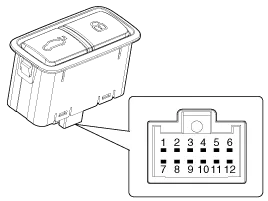
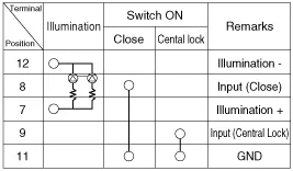
Check for continuity between terminals of the trunk inner switch.
|
| Removal |
| 1. |
Disconnect the negative (-) battery terminal. |
| 2. |
Remove the left trunk trim after opening the trunk.
(Refer to Body - "Trunk Trim") |
| 3. |
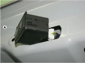
Remove the trunk inner switch (A) after disconnecting the connector.
|
| Installation |
| 1. |
Install the power trunk inner switch after connecting the connector and mounting bolts. |
| 2. |
Install the trunk trim. |
| 3. |
Check that the power trunk module operates normally after connecting the negative (-) battery terminal. |
Other information:
Hyundai Genesis (DH) 2013-2016 Service Manual: Description and Operation
System Overview RPAS (Rear Parking Assist System) is an electronic driving aid that warns the driver to be cautious while parking or driving at low speed. The sensor uses ultrasonic waves to detect objects within proximity of the vehicle. RPAS consists of four RPS sensors which are detecting the obstacles and transmit the result separat
Hyundai Genesis (DH) 2013-2016 Service Manual: Blower Unit Components and Components Location
Component Location Components 1. Seal2. Intake Duct Case3. Intake Door4. Intake Actuator5. Intake Duct Case (A)6. Climate Control Air Filter7. Climate Control Air Filter Cover8. Cluster Ionizer9. Blower Upper Case10. Blower Lower Case11. Power Mosfet12.
Categories
- Manuals Home
- Hyundai Genesis Owners Manual
- Hyundai Genesis Service Manual
- Active Air Flap(AAF) Repair procedures
- Parking Assist Sensor Repair procedures
- Heating, Ventilation and Air Conditioning
- New on site
- Most important about car

Copyright © 2026 www.hgenesisdh.com - 0.0272