Hyundai Genesis (DH): IMS(Integrated Memory System) / Memory power seat unit Schematic Diagrams
| Circuit Diagram |
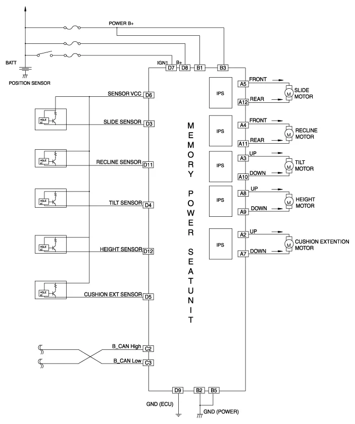
Components NOConnecter AConnecter BConnecter CConnecter D1-B+ (Power)--2Cushion extension moter(Front)GND (Power)B CAN High-3Front tilt motor(UP)B+ (Power)B CAN LowSlide hall sensor4Back motor(Front)--Tilt hall sensor5Slide motor(Front)GND (Power)-Cushion ext hall sensor6-?-Sensor VCC7Cushion extends motor(Rear)-IGN18 Rear height sensor(UP)-B+ (ECU)9 Rear height sensor(Down)-GND (ECU)10Front tilt motor(Down)--11Back motor(Rear)-Recline hall sensor12Slide Moter(Rear)-Height hall sensor13?--14--15--16--17-?18-19-20-
Removal 1. Disconnect the negative (-) battery terminal. 2. Remove the front seat. (Refer to Body - "Front Seat Assembly") 3. Driver settings menu (USM) is Off, 4.
Other information:
Hyundai Genesis (DH) 2013-2016 Service Manual: Components and Components Location
C
Hyundai Genesis (DH) 2013-2016 Service Manual: Photo Sensor Repair procedures
Inspection 1. Turn the ignition switch ON. 2. Connect the GDS. 3. Emit intensive light toward the photo sensor using a lamp, and check the output voltage change. 4. The voltage will rise with higher intensive light and fall with lower intensive light.
Categories
- Manuals Home
- Hyundai Genesis Owners Manual
- Hyundai Genesis Service Manual
- Active Air Flap(AAF) Repair procedures
- Description and Operation
- Body Electrical System
- New on site
- Most important about car
