Hyundai Genesis (DH): Engine Control System / Injector Drive Box (IDB) Schematic Diagrams
Hyundai Genesis (DH) 2013-2016 Service Manual / Engine Control / Fuel System / Engine Control System / Injector Drive Box (IDB) Schematic Diagrams
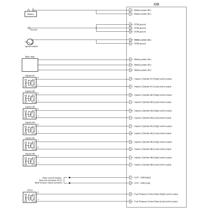
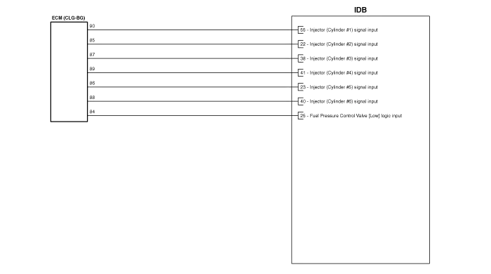
| IDB Terminal And Input / Output signal |

| IDB terminal function |
Connector [C110-IDB]
| Pin No. | Description | Connected to |
| 1 | - | ? |
| 2 | - | ? |
| 3 | - | ? |
| 4 | - | ? |
| 5 | - | ? |
| 6 | - | ? |
| 7 | - | ? |
| 8 | - | ? |
| 9 | - | ? |
| 10 | - | ? |
| 11 | - | ? |
| 12 | - | ? |
| 13 | - | ? |
| 14 | - | ? |
| 15 | - | ? |
| 16 | Injector (Cylinder #3) [Low] control output | Injector (Cylinder #3) |
| 17 | Injector (Cylinder #6) [Low] control output | Injector (Cylinder #6) |
| 18 | Injector (Cylinder #6) [High] control output | Injector (Cylinder #6) |
| 19 | Injector (Cylinder #2) [Low] control output | Injector (Cylinder #2) |
| 20 | Injector (Cylinder #5) [Low] control output | Injector (Cylinder #5) |
| 21 | - | ? |
| 22 | Injector (Cylinder #2) signal input | Engine Control Module (ECM) |
| 23 | Injector (Cylinder #5) signal input | Engine Control Module (ECM) |
| 24 | - | ? |
| 25 | Fuel Pressure Control Valve (FPRV) logic input | Engine Control Module (ECM) |
| 26 | CCP-CAN [Low] | Other control module, Data Link Connector (DLC), Multi-purpose check connector |
| 27 | CCP-CAN [High] | Other control module, Data Link Connector (DLC), Multi-purpose check connector |
| 28 | Battery power (B+) | Ignition switch |
| 29 | Battery power (B+) | Main relay |
| 30 | Battery power (B+) | Main relay |
| 31 | Injector (Cylinder #4) [High] control output | Injector (Cylinder #4) |
| 32 | Injector (Cylinder #1) [High] control output | Injector (Cylinder #1) |
| 33 | Injector (Cylinder #3) [High] control output | Injector (Cylinder #3) |
| 34 | Injector (Cylinder #2) [High] control output | Injector (Cylinder #2) |
| 35 | Injector (Cylinder #5) [High] control output | Injector (Cylinder #5) |
| 36 | - | ? |
| 37 | - | ? |
| 38 | Injector (Cylinder #3) signal input | Engine Control Module (ECM) |
| 39 | - | ? |
| 40 | Injector (Cylinder #6) signal input | Engine Control Module (ECM) |
| 41 | Injector (Cylinder #4) signal input | Engine Control Module (ECM) |
| 42 | Battery power (B+) | Ignition switch |
| 43 | Battery power (B+) | Main relay |
| 44 | Battery power (B+) | Main relay |
| 45 | Fuel Pressure Control Valve (FPRV) [High] control output | Fuel Pressure Control Valve (FPRV) |
| 46 | Injector (Cylinder #4) [Low] control output | Injector (Cylinder #4) |
| 47 | Injector (Cylinder #1) [Low] control output | Injector (Cylinder #1) |
| 48 | ECM ground | Chassis ground |
| 49 | ECM ground | Chassis ground |
| 50 | ECM ground | Chassis ground |
| 51 | - | ? |
| 52 | - | ? |
| 53 | - | ? |
| 54 | - | ? |
| 55 | Injector (Cylinder #1) signal input | Engine Control Module (ECM) |
| 56 | - | ? |
| 57 | - | ? |
| 58 | - | ? |
| 59 | Battery power (B+) | Main relay |
| 60 | Fuel Pressure Control Valve (FPRV) [Low] control output | Fuel Pressure Control Valve (FPRV) |
| IDB Terminal input/output signal |
Connector [C110-IDB]
| Pin No. | Description | Condition | Type | Level |
| 1 | - | ? | ? | ? |
| 2 | - | ? | ? | ? |
| 3 | - | ? | ? | ? |
| 4 | - | ? | ? | ? |
| 5 | - | ? | ? | ? |
| 6 | - | ? | ? | ? |
| 7 | - | ? | ? | ? |
| 8 | - | ? | ? | ? |
| 9 | - | ? | ? | ? |
| 10 | - | ? | ? | ? |
| 11 | - | ? | ? | ? |
| 12 | - | ? | ? | ? |
| 13 | - | ? | ? | ? |
| 14 | - | ? | ? | ? |
| 15 | - | ? | ? | ? |
| 16 | Injector (Cylinder #3) [Low] control output | Idle | Pulse | High: Battery voltage |
| Relay ON | Low: Max. 1.0V | |||
| 17 | Injector (Cylinder #6) [Low] control output | Idle | Pulse | High: Battery voltage |
| Relay ON | Low: Max. 1.0V | |||
| 18 | Injector (Cylinder #6) [High] control output | Idle | Pulse | High: Battery voltage ~ 80V |
| Relay ON | Low: Battery voltage | |||
| 19 | Injector (Cylinder #2) [Low] control output | Idle | Pulse | High: Battery voltage |
| Relay ON | Low: Max. 1.0V | |||
| 20 | Injector (Cylinder #5) [Low] control output | Idle | Pulse | High: Battery voltage |
| Relay ON | Low: Max. 1.0V | |||
| 21 | - | ? | ? | ? |
| 22 | Injector (Cylinder #2) signal input | Idle | Pulse | High: Battery voltage |
| Low: Max. 1.0V | ||||
| 23 | Injector (Cylinder #5) signal input | Idle | Pulse | High: Battery voltage |
| Low: Max. 1.0V | ||||
| 24 | - | ? | ? | ? |
| 25 | Fuel Pressure Control Valve (FPRV) logic input | ? | ? | ? |
| ? | ? | ? | ||
| 26 | CCP-CAN [Low] | Recessive | Pulse | 2.0 ~ 3.0V |
| Dominant | 2.75 ~ 4.5V | |||
| 27 | CCP-CAN [High] | Recessive | Pulse | 2.0 ~ 3.0V |
| Dominant | 2.75 ~ 4.5V | |||
| 28 | Battery power (B+) | IG OFF | DC voltage | Max. 0.5V |
| IG ON | Battery voltage | |||
| 29 | Battery power (B+) | IG OFF | DC voltage | Max. 0.5V |
| IG ON | Battery voltage | |||
| 30 | Battery power (B+) | IG OFF | DC voltage | Max. 0.5V |
| IG ON | Battery voltage | |||
| 31 | Injector (Cylinder #4) [High] control output | Idle | Pulse | High: Battery voltage ~ 80V |
| Relay ON | Low: Battery voltage | |||
| 32 | Injector (Cylinder #1) [High] control output | Idle | Pulse | High: Battery voltage ~ 80V |
| Relay ON | Low: Battery voltage | |||
| 33 | Injector (Cylinder #3) [High] control output | Idle | Pulse | High: Battery voltage ~ 80V |
| Relay ON | Low: Battery voltage | |||
| 34 | Injector (Cylinder #2) [High] control output | Idle | Pulse | High: Battery voltage ~ 80V |
| Relay ON | Low: Battery voltage | |||
| 35 | Injector (Cylinder #5) [High] control output | Idle | Pulse | High: Battery voltage ~ 80V |
| Relay ON | Low: Battery voltage | |||
| 36 | - | ? | ? | ? |
| 37 | - | ? | ? | ? |
| 38 | Injector (Cylinder #3) signal input | Idle | Pulse | High: Battery voltage |
| Low: Max. 1.0V | ||||
| 39 | - | ? | ? | ? |
| 40 | Injector (Cylinder #6) signal input | Idle | Pulse | High: Battery voltage |
| Low: Max. 1.0V | ||||
| 41 | Injector (Cylinder #4) signal input | Idle | Pulse | High: Battery voltage |
| Low: Max. 1.0V | ||||
| 42 | Battery power (B+) | IG OFF | DC voltage | Max. 0.5V |
| IG ON | Battery voltage | |||
| 43 | Battery power (B+) | IG OFF | DC voltage | Max. 0.5V |
| IG ON | Battery voltage | |||
| 44 | Battery power (B+) | IG OFF | DC voltage | Max. 0.5V |
| IG ON | Battery voltage | |||
| 45 | Fuel Pressure Control Valve (FPRV) [High] control output | Idle | DC voltage | Battery voltage |
| Max. 1.0V | ||||
| 46 | Injector (Cylinder #4) [Low] control output | Idle | Pulse | High: Battery voltage |
| Relay ON | Low: Max. 1.0V | |||
| 47 | Injector (Cylinder #1) [Low] control output | Idle | Pulse | High: Battery voltage |
| Relay ON | Low: Max. 1.0V | |||
| 48 | ECM ground | Idle | DC voltage | Max. 50mV |
| 49 | ECM ground | Idle | DC voltage | Max. 50mV |
| 50 | ECM ground | Idle | DC voltage | Max. 50mV |
| 51 | - | ? | ? | ? |
| 52 | - | ? | ? | ? |
| 53 | - | ? | ? | ? |
| 54 | - | ? | ? | ? |
| 55 | Injector (Cylinder #1) signal input | Idle | Pulse | High: Battery voltage |
| Low: Max. 1.0V | ||||
| 56 | - | ? | ? | ? |
| 57 | - | ? | ? | ? |
| 58 | - | ? | ? | ? |
| 59 | Battery power (B+) | IG OFF | DC voltage | Max. 0.5V |
| IG ON | Battery voltage | |||
| 60 | Fuel Pressure Control Valve (FPRV) [Low] control output | Idle | DC voltage | Battery voltage |
| Max. 1.0V |
| Circuit Diagram |
Removal For the vehicle equipped with the immobilizer, the procedures shown below must be performed after replacing the ECM. [In the case of installing used ECM] 1) Perform "ECM Neutral mode" procedure with GDS.
Removal 1. Turn the ignition switch OFF and disconnect the battery negative (-) cable. 2. Remove the ECM & TCM & IDB bracket. (Refer to Engine Control System - "ECM") 3.
Other information:
Hyundai Genesis (DH) 2013-2016 Service Manual: Head Up Display Unit Troubleshooting
T
Hyundai Genesis (DH) 2013-2016 Service Manual: Refrigerant Line Repair procedures
Replacement 1. Discharge refrigerant from refrigeration system. 2. Replace any faulty tubes or hoses. Cap the open fittings immediately to keep moisture or dirt out of the system. 3. Tighten the bolt or nut joint to the specified torque.
Categories
- Manuals Home
- Hyundai Genesis Owners Manual
- Hyundai Genesis Service Manual
- Steering System
- Electric Parking Brake (EPB) Repair procedures
- Body Electrical System
- New on site
- Most important about car

Copyright © 2026 www.hgenesisdh.com - 0.0273