Hyundai Genesis (DH): Engine Control System / Injector Drive Box (IDB) Repair procedures
| Removal |
| 1. |
Turn the ignition switch OFF and disconnect the battery negative (-) cable. |
| 2. |
Remove the ECM & TCM & IDB bracket.
(Refer to Engine Control System - "ECM") |
| 3. |
Disconnect the TCM (B) from the bracket after loosening mounting bolt (A).
|
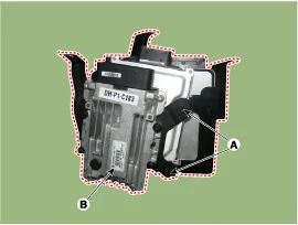
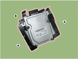
| 4. |
Disconnect the IDB (B) from the bracket after loosening mounting bolt (A).
|
| Installation |
| 1. |
To install, reverse the removal procedure.
|
IDB Terminal And Input / Output signal IDB terminal function Connector [C110-IDB] Pin No.DescriptionConnected to1-?2-?3-?4-?5-?6-?7-?8-?9-?10-?11-?12-?13-?14-?15-?16Injector (Cylinder #3) [Low] control outputInjector (Cylinder #3)17Injector (Cylinder #6) [Low] control outputInjector (Cylinder #6)18Injector (Cylinder #6) [High] control outputInjector (Cylinder #6)19Injector (Cylinder #2) [Low] control outputInjector (Cylinder #2)20Injector (Cylinder #5) [Low] control outputInjector (Cylinder #5)21-?22Injector (Cylinder #2) signal inputEngine Control Module (ECM)23Injector (Cylinder #5) signal inputEngine Control Module (ECM)24-?25Fuel Pressure Control Valve (FPRV) logic inputEngine Control Module (ECM)26CCP-CAN [Low]Other control module, Data Link Connector (DLC), Multi-purpose check connector27CCP-CAN [High]Other control module, Data Link Connector (DLC), Multi-purpose check connector28Battery power (B+)Ignition switch29Battery power (B+)Main relay30Battery power (B+)Main relay31Injector (Cylinder #4) [High] control outputInjector (Cylinder #4)32Injector (Cylinder #1) [High] control outputInjector (Cylinder #1)33Injector (Cylinder #3) [High] control outputInjector (Cylinder #3)34Injector (Cylinder #2) [High] control outputInjector (Cylinder #2)35Injector (Cylinder #5) [High] control outputInjector (Cylinder #5)36-?37-?38Injector (Cylinder #3) signal inputEngine Control Module (ECM)39-?40Injector (Cylinder #6) signal inputEngine Control Module (ECM)41Injector (Cylinder #4) signal inputEngine Control Module (ECM)42Battery power (B+)Ignition switch43Battery power (B+)Main relay44Battery power (B+)Main relay45Fuel Pressure Control Valve (FPRV) [High] control outputFuel Pressure Control Valve (FPRV)46Injector (Cylinder #4) [Low] control outputInjector (Cylinder #4)47Injector (Cylinder #1) [Low] control outputInjector (Cylinder #1)48ECM groundChassis ground49ECM groundChassis ground50ECM groundChassis ground51-?52-?53-?54-?55Injector (Cylinder #1) signal inputEngine Control Module (ECM)56-?57-?58-?59Battery power (B+)Main relay60Fuel Pressure Control Valve (FPRV) [Low] control outputFuel Pressure Control Valve (FPRV) IDB Terminal input/output signal Connector [C110-IDB] Pin No.
Description The Electronic Throttle Control (ETC) System consists of a throttle body with an integrated control motor and throttle position sensor (TPS).
Other information:
Hyundai Genesis (DH) 2013-2016 Service Manual: Auto Head Lamp Leveling Unit Description and Operation
Description According to driving environment and loading state of vehicle, head lamp lighting direction is changed to keep the driver's visibility range and to protect the driver's vision from glare, aiming at safety driving. Sensor integrated ECU mounting on the rear center arm drives the actuator mounting on the head lamp since sens
Hyundai Genesis (DH) 2013-2016 Service Manual: Photo Sensor Description and Operation
Description The photo sensor is located in the right side of the inside rearview mirror. he integrated rain sensor is located in the right side of the inside rearview mirror. The integrated rain sensor is a multifunctional sensor which combines the photo sensor and auto light sensor, and has a built-in photovoltaic diode (for detecting t
Categories
- Manuals Home
- Hyundai Genesis Owners Manual
- Hyundai Genesis Service Manual
- Body Electrical System
- Repair procedures
- Body (Interior and Exterior)
- New on site
- Most important about car
