Hyundai Genesis (DH): Engine Control System / Engine Control Module (ECM) Repair procedures
| Removal |
For the vehicle equipped with the immobilizer, the procedures shown below must be performed after replacing the ECM.
[In the case of installing used ECM]
1) Perform "ECM Neutral mode" procedure with GDS. (Refer to "Immobilizer" in BE group)
2) After finishing "ECM Neutral mode", perform "Key teaching" procedure with GDS. (Refer to "Immobilizer" in BE group)
[In the case of installing new ECM]
Perform "Key teaching" procedure with GDS. (Refer to "Immobilizer" in BE group)
|

For the vehicle equipped with the smart key system (Button
start), the procedures shown below must be performed after replacing the
ECM.
[In the case of installing used ECM]
1) Perform "ECM Neutral mode" procedure with GDS. (Refer to "Smart key" in BE group)
2) After finishing "ECM Neutral mode", insert the key (or
press the start button) and turn it to the IGN ON and OFF position. Then
the ECM learns the smart key information automatically.
[In the case of installing new ECM]
Insert the key (or press the start button) and turn it to the
IGN ON and OFF position. Then the ECM learns the smart key information
automatically.
|
| 1. |
Turn ignition switch OFF and disconnect the negative (-) battery cable. |
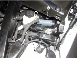
| 2. |
Remove the cover. |
| 3. |
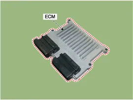
Disconnect the ECM connector (A) and the IDB connector (B). |
| 4. |
Disconnect the TCM connector (C).
|
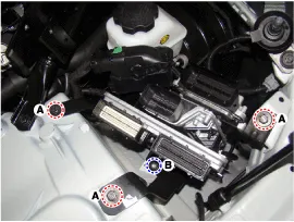
| 5. |
Remove the ECM & TCM & IDB bracket installation bolts (A) and nut (B).
|
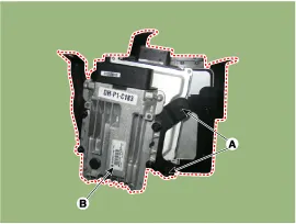
| 6. |
Disconnect the TCM (B) from the bracket after loosening mounting bolt (A).
|
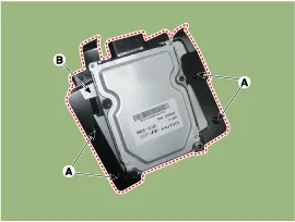
| 7. |
Disconnect the ECM (B) from the bracket after loosening mounting nut (A).
|
| Installation |
In the case of the vehicle equipped with immobilizer, perform
"Key Teaching" procedure together (Refer to "Immobilizer" in BE group). |

| 1. |
To install, reverse the removal procedure.
|
| ECM Problem Inspection Procedure |
| 1. |
TEST ECM GROUND CIRCUIT: Measure resistance between ECM and
chassis ground using the backside of ECM harness connector as ECM side
check point. If the problem is found, repair it.
|
| 2. |
TEST ECM CONNECTOR: Disconnect the ECM connector and visually
check the ground terminals on ECM side and harness side for bent pins
or poor contact pressure. If the problem is found, repair it. |
| 3. |
If problem is not found in Step 1 and 2, the ECM could be
faulty. If so, replace the ECM with a new one, and then check the
vehicle again. If the vehicle normally operates, the problem could be
found in the ECM. |
| 4. |
RE-TEST THE ORIGINAL ECM: Install the original ECM (may be
broken) into a known-good vehicle and check the vehicle. If the problem
occurs again, replace the original ECM with a new one. If problem does
not occur, it is an intermittent problem (Refer to |
ECM Terminal and Input/Output signal ECM Terminal Function Connector [E100-A] Pin No.DescriptionConnected to1-?2-?3-?4-5Power groundChassis Ground6Power groundChassis Ground7-?8-?92nd CAN [High]Multi-Purpose Check Connector10CAN [High]Other control module, Data Link Connector (DLC), Multi-Purpose Check Connector11Fuel Tank Pressure Sensor (FTPS) signal inputFuel Tank Pressure Sensor (FTPS)12-13Oil pressure switch signal inputOil Pressure Sensor (OPS)14Sensor power (+5V)Accelerator Position Sensor (APS) 115Sensor power (+5V)A/C Pressure Transducer (APT)Oil Pressure Sensor (OPS)Rail Pressure Sensor (RPS)16-17-18-?19-?20-21Brake Switch 2 signal inputBrake Switch22-?23-?24Alternator PWM signal input [FR]Alternator25-26-?27Battery power (B+)Ignition Switch28Rail Pressure Sensor (RPS) signal inputRail Pressure Sensor (RPS)29-?30Power groundChassis Ground31-?32-?33-?342nd CAN [Low]Multi-Purpose Check Connector35CAN [Low]Other control module, Data Link Connector (DLC), Multi-Purpose Check Connector36-?37Sensor groundRail Pressure Sensor (RPS)38Accelerator Position Sensor (APS) 1 signal inputAccelerator Position Sensor (APS) 139-?40-?41-42-43Brake lamp signal inputBrake lamp44-?45-?46-?47-?48-49-?50-?51-?52Battery power (B+)Battery53-?54-?55Power groundChassis Ground56-?57-58-?59Sensor groundAccelerator Position Sensor (APS) 260Sensor groundAccelerator Position Sensor (APS) 161Sensor groundFuel Tank Pressure Sensor (FTPS)Oil Pressure Sensor (OPS)62-63Sensor groundA/C Pressure Transducer (APT)64-?65Sensor Power (+5V)Fuel Tank Pressure Sensor (FTPS)66-67A/C Pressure Transducer (APT) signal inputA/C Pressure Transducer (APT)68Accelerator Position Sensor (APS) 2 signal inputAccelerator Position Sensor (APS) 269Power Steering Pressure Sensor (PSPS) signal input70Engine speed signal outputPower Distribution Module (PDM)71Cooling Fan Relay [High] control outputCooling Fan Relay [High]72Alternator PWM signal output (COM)Alternator73-?74Immobilizer communication lineSmart Key Control Module75Battery power (B+)Main Relay76-?77Battery power (B+)Battery78-79-?80Power groundChassis ground81-?82-?83-?84-?85-?86-?87LIN (Local Interconnect Network) Serial Bus LineBattery Sensor88-?89-?90Sensor power (+5V)Accelerator Position Sensor (APS) 291-92-?93Starter Relay control outputStarter Relay94Main Relay control outputMain Relay95Fuel pump Relay control outputFuel pump Relay 96Canister Close Valve (CCV) control outputCanister Close Valve (CCV)97-?98Dual stage oil pumpVariable Intake Solenoid (VIS) valve 299Battery power (B+)Main Relay100Battery power (B+)Main Relay Connector [C100-B] Pin No.
IDB Terminal And Input / Output signal IDB terminal function Connector [C110-IDB] Pin No.DescriptionConnected to1-?2-?3-?4-?5-?6-?7-?8-?9-?10-?11-?12-?13-?14-?15-?16Injector (Cylinder #3) [Low] control outputInjector (Cylinder #3)17Injector (Cylinder #6) [Low] control outputInjector (Cylinder #6)18Injector (Cylinder #6) [High] control outputInjector (Cylinder #6)19Injector (Cylinder #2) [Low] control outputInjector (Cylinder #2)20Injector (Cylinder #5) [Low] control outputInjector (Cylinder #5)21-?22Injector (Cylinder #2) signal inputEngine Control Module (ECM)23Injector (Cylinder #5) signal inputEngine Control Module (ECM)24-?25Fuel Pressure Control Valve (FPRV) logic inputEngine Control Module (ECM)26CCP-CAN [Low]Other control module, Data Link Connector (DLC), Multi-purpose check connector27CCP-CAN [High]Other control module, Data Link Connector (DLC), Multi-purpose check connector28Battery power (B+)Ignition switch29Battery power (B+)Main relay30Battery power (B+)Main relay31Injector (Cylinder #4) [High] control outputInjector (Cylinder #4)32Injector (Cylinder #1) [High] control outputInjector (Cylinder #1)33Injector (Cylinder #3) [High] control outputInjector (Cylinder #3)34Injector (Cylinder #2) [High] control outputInjector (Cylinder #2)35Injector (Cylinder #5) [High] control outputInjector (Cylinder #5)36-?37-?38Injector (Cylinder #3) signal inputEngine Control Module (ECM)39-?40Injector (Cylinder #6) signal inputEngine Control Module (ECM)41Injector (Cylinder #4) signal inputEngine Control Module (ECM)42Battery power (B+)Ignition switch43Battery power (B+)Main relay44Battery power (B+)Main relay45Fuel Pressure Control Valve (FPRV) [High] control outputFuel Pressure Control Valve (FPRV)46Injector (Cylinder #4) [Low] control outputInjector (Cylinder #4)47Injector (Cylinder #1) [Low] control outputInjector (Cylinder #1)48ECM groundChassis ground49ECM groundChassis ground50ECM groundChassis ground51-?52-?53-?54-?55Injector (Cylinder #1) signal inputEngine Control Module (ECM)56-?57-?58-?59Battery power (B+)Main relay60Fuel Pressure Control Valve (FPRV) [Low] control outputFuel Pressure Control Valve (FPRV) IDB Terminal input/output signal Connector [C110-IDB] Pin No.
Other information:
Hyundai Genesis (DH) 2013-2016 Service Manual: Repair procedures
Diagnosis With GDS 1. BSD system defects can be quickly diagnosed with the GDS. GDS operates actuator quickly to monitor, input/output value and self diagnosis. 2. Connect the cable of GDS to the data link connector in driver side crash pad lower panel, and turn on the GDS.
Hyundai Genesis (DH) 2013-2016 Service Manual: Power Mosfet Repair procedures
Inspection 1. Turn the ignition switch ON. 2. Manually operate the control switch and control the voltage of the blower motor. 3. Select the control switch to raise the voltage until high speed. Specification Fan Speed (Manual)Motor Voltage (V)13.
Categories
- Manuals Home
- Hyundai Genesis Owners Manual
- Hyundai Genesis Service Manual
- Starter Repair procedures
- Engine Electrical System
- Steering System
- New on site
- Most important about car
